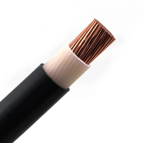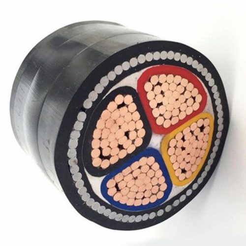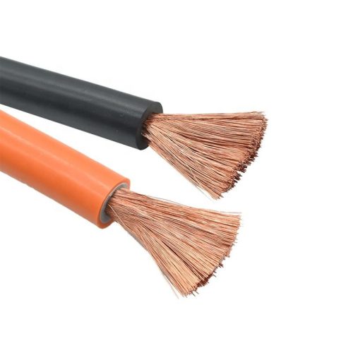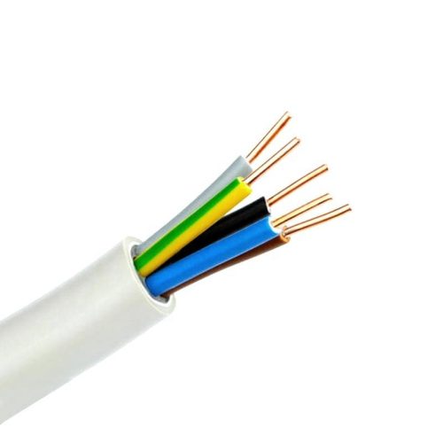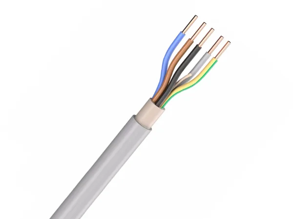
NYM-J and NYM-O are premium PVC-sheathed installation cables designed for fixed electrical installations in residential, commercial, and industrial environments. These versatile cables comply with German VDE standards and European regulations, offering reliable performance and safety for a wide range of applications. The main distinction between the two variants is that NYM-J cables include a yellow/green protective earth conductor, while NYM-O cables do not.
Applications
These cables are suitable for:
- Industrial and domestic electrical installations
- Fixed wiring in dry, damp, and wet environments
- Installation above, on, in, and under plaster
- Installation in masonry walls and concrete (not for direct embedding in vibration-compacted or tamped concrete)
- Interior installations for houses and premises
- Buildings with special characteristics
- Temporary and provisional installations
- Electrical installations on furniture and equipment
Note: Outdoor application is permitted only when the cable is protected against direct sunlight exposure.
Standards and Approvals
NYM-J/NYM-O cables comply with the following standards and regulations:
- DIN VDE 0250-204
- DIN VDE 0281-1
- DIN VDE 0482-332-1-2 / DIN EN 60332-1-2 / IEC 60332-1-2 (flame retardant)
- EU CPR Regulation 305/2011 and EN 50575
- CE marked in accordance with the EC Low-Voltage Directive 73/23/EEC and 93/68/EEC
- RoHS compliant
- UNE 21031-4 and HD 21.4S2
- IEC 60227-4
Technical Characteristics
- Nominal voltage: 300/500 V
- Test voltage: 2000 V AC
- Maximum conductor temperature: +70°C
- Temperature range during installation: +5°C to +50°C
- Temperature range after installation (fixed): -40°C to +70°C
- Minimum bending radius (fixed installation): 4 × outer diameter
- Radiation resistance: up to 80 × 10⁶ cJ/kg (up to 80 Mrad)
- Flame properties: Self-extinguishing and flame retardant
- Insulation resistance: >20 MΩ × km
Cable Construction
- Conductor: Solid or stranded plain copper according to DIN VDE 0295 Class 1 or Class 2 / IEC 60228
- 1.5-10 mm²: solid conductor
- 16-35 mm²: stranded conductor
- Insulation: PVC type TI1 according to DIN VDE 0207-363-3 / DIN EN 50363-3
- Core identification: Color coded according to DIN VDE 0293-308
- 1 core: black or green-yellow
- 2-5 cores: color coded
- 7-12 cores: black cores with consecutive white numbering
- Stranding: Conductors stranded in layers with optimal lay lengths
- Filling compound: Core sheathing for multi-core cables
- Outer sheath: Special PVC type TM1 according to DIN VDE 0207-363-4-1 / DIN EN 50363-4-1
- Sheath color: Grey (RAL 7035)
- Special features: NYM-J includes a yellow/green protective conductor (earth)
Installation Guidelines
- These cables are designed for fixed installation only
- Not recommended for direct embedding in compacted concrete
- For outdoor applications, ensure protection from direct sunlight
- Maintain minimum bending radius during installation
- Ensure proper termination and connection methods are used
- Follow local electrical codes and regulations for installation
Technical Data Tables (Excerpt)
NYM-O Cable Specifications (Selection)
| Part No. | No. of Cores × Cross Section (mm²) | Approx. Outer Diameter (mm) | Copper Weight (kg/km) | Approx. Cable Weight (kg/km) |
|---|---|---|---|---|
| 0939001 | 1 × 1.5 | 5.4 | 14.4 | 40.0 |
| 0939007 | 2 × 1.5 | 8.7 | 29.0 | 170.0 |
| 0939009 | 4 × 1.5 | 9.8 | 58.0 | 160.0 |
| 0939010 | 4 × 2.5 | 11.3 | 96.0 | 230.0 |
| 0939011 | 4 × 4.0 | 13.0 | 154.0 | 330.0 |
| 0939012 | 4 × 6.0 | 15.1 | 230.0 | 460.0 |
| 0939013 | 4 × 10 | 17.6 | 384.0 | 680.0 |
NYM-J Cable Specifications (Selection)
| Part No. | No. of Cores × Cross Section (mm²) | Approx. Outer Diameter (mm) | Copper Weight (kg/km) | Approx. Cable Weight (kg/km) |
|---|---|---|---|---|
| 0939055 | 1 × 2.5 | 6.0 | 24.0 | 70.0 |
| 0939058 | 4 × 1.5 | 9.8 | 58.0 | 160.0 |
| 0939059 | 4 × 2.5 | 11.3 | 96.0 | 230.0 |
| 0939060 | 4 × 4.0 | 13.0 | 154.0 | 330.0 |
| 0939061 | 4 × 6.0 | 15.1 | 230.0 | 460.0 |
| 0939063 | 4 × 16 | 21.3 | 614.0 | 1048.0 |
| 0939072 | 7 × 1.5 | 11.5 | 101.0 | 235.0 |
Note: re = round solid conductor; rm = round stranded conductor. Complete tables available upon request.
Notes
- All dimensions and weights are approximate values
- Technical specifications may be subject to change without prior notice as part of continuous improvement processes
- Proper selection of cable size should consider current load, voltage drop, and short-circuit current
- For specific applications or custom requirements, please consult with our technical department
- AWG numbers provided in some references are approximate conversions and are for reference only