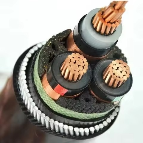
Application:
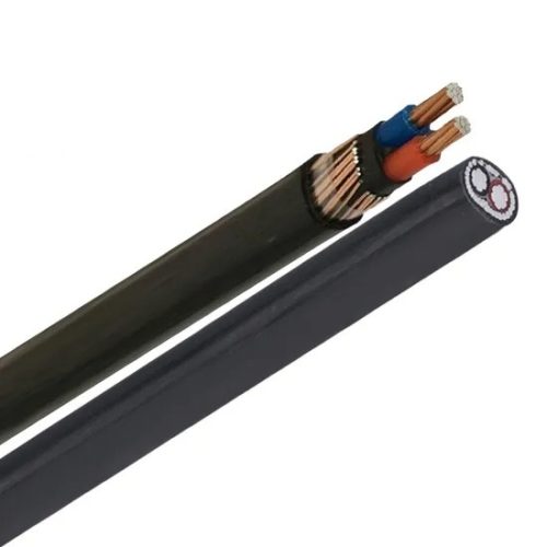
To be used for power distribution in medium voltage, as transformer feeders in substations. In power plants, industrial and operation installations, in residential areas and mining installations, in dry or wet locations, fixed installed in air, directly buried in the ground or in ducts, where require higher mechanical protection.
Construction:
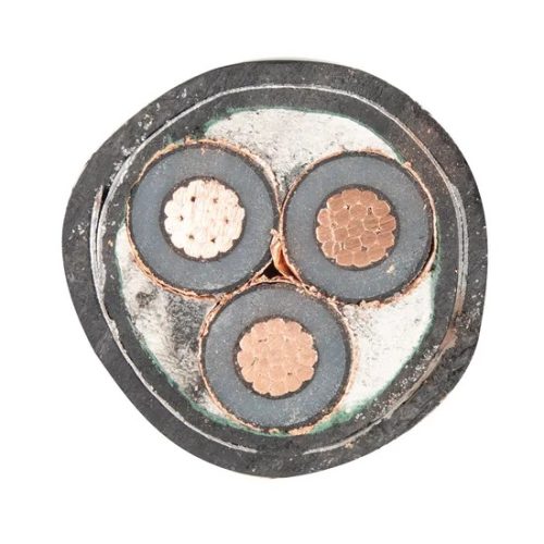
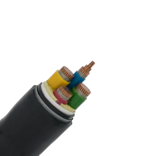
1. Conductor – Plain annealed class 2 compacted copper
2. Conductor screen – Semi-conductive compound
3. Insulation – Cross linked polyethylene (XLPE)
4. Insulation screen – Semi-conductive compound
5. Metallic screen – Plain annealed copper tape
6. Filler – Non-hygroscopic material
7. Binder tape – Non-hygroscopic material tape
8. Separation layer – Polyvinyl chloride compound (PVC)
9. Armor – Galvanized steel wire wires
10. Binder tape – Non-hygroscopic material tape
11. Outer sheath – Polyvinyl chloride compound (PVC)
Cross Section:
3 core; 16~400mm2
Temperature characteristics:
Conductor operating temperature: -15ºC~90ºC
Min. temperatrue laying condition: 0ºC
Conductor emergency operating temperature: 105ºC
Conductor short-circuit operating temperature (5s): 250ºC
Electrical Characteristics:
Rated voltage: 3.6/6(7.2) kV
AC High voltage test: 2.5U0 for 30min
Partial Discharge at 1.73 U0: 5PC or better
Color:
Core identification: Red, Yellow, Blue color strip along the phase core or according to the customer’s request
Outer sheath: Black or according to customer requirements
Standard:
Cable design: IEC 60502-2
Conductor: IEC 60228
3.6/6(7.2)kV,3.6/6.6(7.2)kV,Three Cores,Al or Cu/XLPE/CTS/STA/PVC Armoured Power Cable
| No.X Nominal Cross Section of Conductor | Nominal Diameter of Conductor | Nominal Thickness of Insulation | Nominal Thickness of Copper Tape Screen | Nominal Thickness of Inner Sheath | Nominal Thickness of Steel Tape Armouring | Nominal Thickness of PVC Sheath | Approx. Overall Diameter | Approx. Weight | |
|---|---|---|---|---|---|---|---|---|---|
| Al Conductor | Cu Conductor | ||||||||
| No. X mm2 | mm | mm | mm | mm | mm | mm | mm | kg/m | kg/m |
| 3 X 25 | 6.0 | 2.5 | 0.1 | 1.2 | 0.2 | 1.9 | 37.9 | 1.87 | 2.32 |
| 3 X 35 | 6.9 | 2.5 | 0.1 | 1.3 | 0.5 | 2.0 | 41.5 | 2.10 | 2.73 |
| 3 X50 | 8.2 | 2.5 | 0.1 | 1.3 | 0.5 | 2.0 | 44.3 | 2.37 | 3.22 |
| 3 X 70 | 9.7 | 2.5 | 0.1 | 1.4 | 0.5 | 2.1 | 47.9 | 2.77 | 4.00 |
| 3 X 95 | 11.3 | 2.5 | 0.1 | 1.4 | 0.5 | 2.2 | 51.6 | 3.21 | 4.91 |
| 3 X 120 | 12.8 | 2.5 | 0.1 | 1.5 | 0.5 | 2.4 | 55.4 | 3.69 | 5.84 |
| 3 X 150 | 14.2 | 2.5 | 0.1 | 1.5 | 0.5 | 2.5 | 58.6 | 4.15 | 6.85 |
| 3 X 185 | 15.9 | 2.5 | 0.1 | 1.5 | 0.5 | 2.6 | 62.5 | 4.73 | 8.11 |
| 3 X 240 | 18.3 | 2.6 | 0.1 | 1.6 | 0.5 | 2.7 | 68.5 | 5.62 | 10.05 |
| 3 X 300 | 20.4 | 2.8 | 0.1 | 1.7 | 0.5 | 2.9 | 74.5 | 6.55 | 12.11 |
| 3 X 400 | 23.2 | 3.0 | 0.1 | 1.9 | 0.8 | 3.2 | 83.6 | 8.78 | 15.86 |
| 3 X 500 | 26.4 | 3.2 | 0.1 | 2.1 | 0.8 | 3.4 | 93.0 | 10.52 | 18.85 |