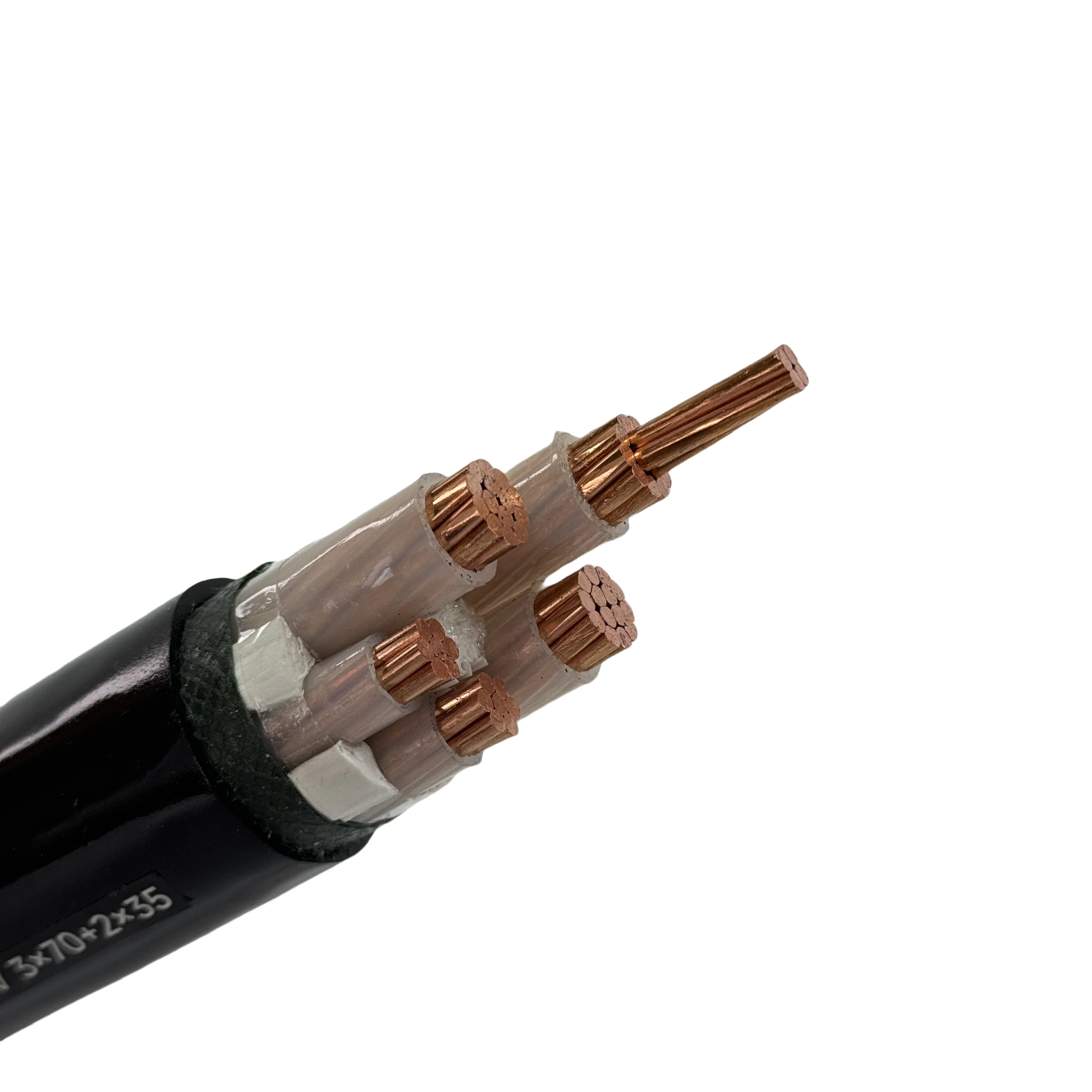
Подробное Описание
What 0.6/1 kV XLPE Cable Is Used For
The 0.6/1 kV class is the working voltage of low-voltage distribution: the cable that runs from a switchboard to a sub-board, from a sub-board to a machine, or from a distribution board to a charging pile. It is not a transmission cable and not a control cable — it carries the load current at the voltage the equipment actually uses.
What separates this cable from a PVC distribution cable is the insulation. XLPE — cross-linked polyethylene — holds 90 °C at the conductor where PVC is limited to 70 °C, and it tolerates a short-circuit temperature of up to 250 °C. Both numbers translate into either more current for the same cross-section or a longer life for the same current.
Construction: Copper, XLPE, Filler, and Sheath
The cable is built in five layers, and the sequence matters as much as the materials:
- Conductor — oxygen-free copper at 99.9% purity, stranded. The low resistance is what keeps the voltage drop inside the limit on a long distribution run.
- Insulation — XLPE, extruded at a low-eccentricity wall around each core. The evenness of the wall is the property that resists impulse breakdown; a nominal thickness with a thin side fails at the thin side.
- Filler — a tensile-resistant filler holds the core assembly together. It is what allows the cable to be pulled into a duct without the cores spreading.
- Water barrier — an internal water-blocking wrap sits under the sheath, so moisture that enters through a sheath damage is stopped before it travels along the cable to the conductor.
- Sheath — PVC in black, applied over the assembly. It is the mechanical and moisture barrier, and it carries the metre marking and the product designation.
Electrical and Installation Limits
| Parameter | Value |
|---|---|
| Rated voltage (U0/U) | 0.6/1 kV |
| Maximum working voltage | 1.2 kV |
| Test voltage | 3500 V |
| Conductor | Oxygen-free copper, 99.9% |
| Insulation | XLPE |
| Sheath | PVC, black |
| Operating temperature | −5 °C to +70 °C ambient; 70–90 °C conductor |
| Short-circuit temperature | 160–250 °C, max 5 s |
| Minimum installation temperature | 0 °C |
| Minimum bending radius | 15 × diameter |
| Maximum pulling stress | 50 N/mm² |
| Core count | 1 to 5 |
| Cross-section | 2×10 to 4×400 mm² |
Two of these limits are installation limits rather than electrical ones, and they are the ones that fail on site. The 0 °C minimum installation temperature means the cable should not be bent cold; the 15 × diameter bending radius means a tight pull around a corner needs a larger sweep or a pre-formed bend.
Reading the Cross-Section and Core Range
The range runs from 2×10 mm² to 4×400 mm² across one-, two-, three-, four-, and five-core builds. The pattern is straightforward: a single-core cable for a feeder run, a three-core cable for a three-phase circuit without a neutral, a four-core cable for three-phase plus neutral, and a five-core cable where a separate earth core is carried.
The cross-section is not selected from the current alone. A cable installed in air dissipates heat differently from a cable buried in soil, and a cable grouped with others in a duct runs hotter than a single cable. The load current, the run length, and the installation method are chosen together.
Standards, Lengths, and Ordering
The source data lists IEC 60227-5, GB/T 9330-2008, and a conductor to IEC 60228. Because acceptance on a project is measured against the standard named in the specification, the governing standard should be stated on the contract drawing before the order is placed rather than inferred from the cable type.
Supply is a 100 m coil, with lengths below 100 m as measured cut lengths. The sheath carries metre marking, so a cut length can be verified on site.
To specify the cable, five items decide the build: the number of cores, the cross-section, the installation method, the run length, and whether armour is required. Send them through the enquiry form on this page, together with the standard the project is inspected against, and the build is confirmed against those inputs.