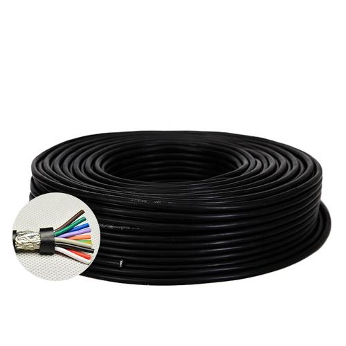
Detailed Description
Why Double Shield? The Physics of Electromagnetic Interference
Every industrial environment has electromagnetic noise. Motors hum at 50/60 Hz. VFDs switch at 4–16 kHz with harmonics into the MHz range. Contactors arc. Welders pulse. Mobile phones and Wi-Fi transmit at 2.4 and 5 GHz.
A single-layer braid shield is a woven mesh of copper wires. It blocks low frequencies well — the braid acts as a continuous conductive tube for wavelengths much larger than the braid gap. But at frequencies above ~30 MHz, where the wavelength shrinks below 10 meters, the millimeter-scale gaps between braid strands become effective apertures — tiny windows through which high-frequency noise leaks.
A foil shield has zero gaps. 100% optical coverage. It blocks high frequencies perfectly. But foil is mechanically fragile — it tears under repeated flexing, and it cannot carry significant shield current.
Double-shielded = foil (100% coverage, high-frequency specialist) + braid (mechanical robustness, low-frequency specialist). Each layer does what it does best. Together they provide full-spectrum EMI protection that neither can achieve alone.Transfer Impedance — The Engineering Proof
| Shield Configuration | Zₜ at 30 MHz | Zₜ at 100 MHz | Notes |
|---|---|---|---|
| Unshielded | >1 000 mΩ/m | >1 000 mΩ/m | No EMI protection |
| Single braid 80% | ~100 mΩ/m | ~300 mΩ/m | Standard industrial — adequate for motor power |
| Single braid 90% | ~60 mΩ/m | ~200 mΩ/m | Better — adequate for control signals |
| Foil + drain wire | ~200 mΩ/m | ~500 mΩ/m | Good at low freq; drain wire inductance limits HF |
| Foil + braid (double) | ≤15 mΩ/m | ≤50 mΩ/m | Full-spectrum — military/medical grade |
| Solid copper tube | ~1 mΩ/m | ~5 mΩ/m | Best possible — rigid coax, not flexible |
The key insight: at 30 MHz, double-shielded cable is 6–13× better than single-braid alternatives. This difference is not theoretical — it is the difference between a clean encoder signal and one with intermittent position errors.
Layer-by-Layer Construction
Layer 1: Core Assembly
Class 5 stranded conductors with PVC, PP, or PE insulation. PP and PE options provide lower capacitance between cores and to shield — important for high-speed data signals (RS-485, CAN bus) where cable capacitance limits maximum transmission distance.
Layer 2: Inner PET Wrap
Separates the core assembly from the foil shield. Without this layer, individual core insulation would be in direct contact with the foil's metal surface — creating localized high-capacitance points that degrade signal integrity.
Layer 3: Inner Foil Shield
Aluminum/polyester foil, 100% coverage, wrapped metal-side-in. A tinned copper drain wire runs the length of the cable in continuous contact with the foil surface — providing a convenient termination point. For full RF performance, the foil itself must make 360° contact at the connector.
Layer 4: Intermediate PET Wrap
A thin PET tape between foil and braid. This is a wear surface — it absorbs the mechanical movement of the braid during flexing, preventing the braid strands from cutting through the fragile foil. Without this layer, double-shielded cables lose their high-frequency performance within thousands of flex cycles as the braid abrades the foil.
Layer 5: Outer Braid Shield
Tinned copper braid, ≥85% optical coverage. Carries shield current, provides mechanical protection for the foil, and blocks low-frequency EMI. The braid is terminated at both ends through 360° EMC cable glands or connector backshells.
Layer 6: Outer Jacket
PVC (standard), NBR-PVC (enhanced oil), or PUR (premium — halogen-free, oil/UV rated). Compresses the shield layers together, maintaining consistent electrical contact between foil and braid.
Shield Termination — Grounding Both Layers Correctly
Double-shielded cable requires careful termination:
- Inner foil drain wire: Connect at the signal-source end only (e.g., at the encoder, not at the drive). Single-point grounding prevents ground loop currents from flowing through the foil
- Outer braid: Connect at both ends through 360° EMC cable glands. The braid carries fault current and provides the primary EMI barrier — both-end grounding creates a low-impedance path to ground
- Separation at termination: Strip the outer jacket back 30–40 mm. Fold the braid back over the jacket. Strip the inner jacket/foil back 15–20 mm from the braid fold point. The foil and braid must NOT touch at the termination point — they are electrically separate shield layers
- Pigtail warning: A pigtail (drain wire only) termination on the braid adds series inductance that nullifies high-frequency shielding. A 50 mm pigtail at 100 MHz has ~50 nH inductance — equivalent to 31 Ω at that frequency. Always use 360° termination for the braid
Why Choose Yichi Cable Double-Shielded?
- PET inter-shield separator as standard: The wear layer between foil and braid is included on every double-shielded cable — prevents the #1 failure mode (braid cutting through foil)
- Transfer impedance tested: Every production batch is tested for Zₜ at 30 MHz — we publish the batch result, not a calculated estimate
- Application-matched insulation: PVC for general signal, PP for low-capacitance (long RS-485 runs), PE for high-frequency — we help you select based on signal type and cable length
- Drain wire on both shields: Termination flexibility without sacrificing shield performance — standard on all configurations
- Custom drain wire configuration: Need the foil drain brought out separately from the braid termination? We build it that way — reduces ground loop risk in sensitive analog applications