Detailed Description
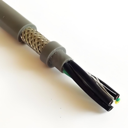
Shielded Drag Chain Cable — More Than Just Adding a Braid
Many engineers think "shielded cable" means the same unshielded cable with copper braid wrapped around it. In reality, adding a shield to a flexing cable introduces entirely new failure modes that must be engineered out:
- Shield fatigue: Copper braid strands, individually only 0.10–0.15 mm thick, fracture under repeated bending — especially if the shield is applied directly over the core assembly without a stabilizing inner layer
- Shield migration: Under high acceleration, the braid can telescope (slide longitudinally along the cable), bunching up at carrier clamp points and exposing sections of the core
- Capacitance increase: The shield adds measurable capacitance between each core and ground — in VFD applications, this increases the cable's charging current and reflected wave voltage at the motor terminals
Choosing the Right Shield Type
Selecting the wrong shield for your application either over-engineers the cable (adding cost, weight, and bend radius) or under-protects it (resulting in EMI-induced faults). This guide maps shield type to application:
| Shield Type | Coverage | Best For | EMI Frequency | Flex Life Impact | Cost |
|---|---|---|---|---|---|
| Foil Only (Al/PET) | 100% (wrap) | High-frequency EMI (>30 MHz): encoder pulses, Ethernet, RF noise from VFD switching | 30 MHz–1 GHz | -30% (foil fatigues faster than braid) | Lowest |
| Braid Only (TC Braid) | 80–90% | Low-frequency EMI (<30 MHz): 50/60 Hz motor hum, VFD fundamental, contactor noise | 10 kHz–30 MHz | Baseline (5M cycles) | Moderate |
| Foil + Braid (Dual) | 100% foil + 85% braid | Full-spectrum EMI: encoder + VFD in same carrier, military/medical EMI compliance | 10 kHz–1 GHz | Baseline (5M–10M cycles) | Higher |
| Spiral Shield (TC Spiral) | 90%+ | Maximum flexibility applications where EMI is moderate; robotics, frequent tight bends | 10 kHz–100 MHz | +20% (spiral moves with cable better than braid) | Moderate |
How We Protect the Shield — The Difference Between Good and Great
Anti-Torsion Core Stranding
Before the shield is applied, the core assembly is stranded with a specific alternating lay direction. This anti-torsion structure prevents the core bundle from rotating inside the shield when the cable bends — rotation that would otherwise twist and fatigue the braid at specific points.
Inner Stabilizing Layer
A PET fleece or non-woven tape is applied over the stranded core assembly before the shield. This layer:
- Provides a uniform cylindrical surface for the braid to grip
- Prevents individual core insulation from extruding between braid strands during tight bends
- Absorbs minor core movement, isolating the shield from internal dynamics
Braid Bonding (Optional)
For severe flex applications, the braid is lightly bonded to the inner stabilizing layer with a flexible adhesive. This prevents the braid from sliding relative to the core — the primary cause of shield telescoping in high-acceleration carriers. The bond is designed to flex with the cable without cracking.
Shield Grounding — Getting It Right
Improper shield grounding is the most common cause of "the shielded cable didn't help" complaints:
Low-Frequency Signals (< 100 kHz): Single-End Grounding
Ground the shield at the controller/amplifier end only. Leave the motor/sensor end ungrounded. This prevents ground loop currents from flowing through the shield at 50/60 Hz.
Exception: If the motor/sensor is electrically isolated from ground (floating), ground the shield at both ends — but verify that no potential difference exists between the two grounding points.High-Frequency Signals (> 1 MHz): Both-End Grounding
Encoder pulses, Ethernet, and fieldbus signals require both-end grounding to create a low-impedance path for high-frequency noise currents. The key requirement: the two ground points must be at the same potential, connected through the machine's equipotential bonding system.
Practical Implementation
- Use 360° EMC cable glands at both carrier exit points — not pigtail drain wires, which create an inductive stub that nullifies high-frequency shielding
- For foil-shielded cables: the drain wire is for shield termination convenience only. The foil must make direct 360° contact with the gland body for effective RF shielding
- For braid-shielded cables: fold the braid back over the gland's conical insert. When the gland nut is tightened, the insert compresses the braid against the connector body for a full 360° low-impedance connection
Jacket Material Selection for Shielded Cables
The jacket serves a dual role in shielded cables — environmental protection AND compression of the shield against the inner layers for consistent electrical contact:
- PVC: Cost-effective for standard indoor environments. Moderate oil resistance. Temperature -5°C to +70°C moving. Most common choice.
- PUR: For oil, coolant, UV, and outdoor environments. Halogen-free. Maintains shield compression force at low temperatures (-30°C) where PVC becomes stiff.
- TPE: For extreme low-temperature flexibility (-40°C moving). Softer than PUR; verify mechanical protection is adequate for your environment.
Why Choose Yichi Cable Flexible Shielded?
- We help you select the right shield: Tell us your EMI environment (what's nearby, what signal types) and we recommend the shield type — not the most expensive, the right one
- Pre-tested shield integrity: Every production batch is tested for shield continuity and coverage percentage in our CNAS-accredited lab
- Shield grounding support: We provide application notes for your specific connector and gland setup — not just a cable, a solution
- Custom builds: Mixed-gauge (power + signal in one cable), custom shield type, jacket, color, and marking — built to order in 7–15 days