Detailed Description
What Is TRVVSP Cable?
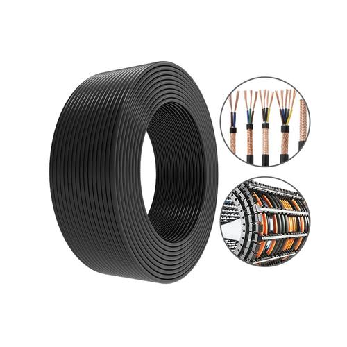
TRVVSP cable is a high-flex, twisted pair, shielded cable built for drag chain signal transmission. The name describes its core construction: drag chain, flexible conductor, PVC insulation, PVC jacket, twisted pair, and shield. It is used where servo motor encoders and other low-voltage signal circuits must keep working while the cable moves continuously inside a cable carrier.
The problem it solves is electrical noise. In a machine, signal cables often run beside motor power cables, VFD output leads, and servo drive cables. Those power conductors create electromagnetic interference that can distort encoder pulses or low-voltage signal data. TRVVSP uses twisted pairs and a tinned copper braid shield to reduce that interference. Some constructions also add aluminum foil with 125% overlap over the pairs. The result is a cable intended for signal integrity in moving automation equipment, not a general-purpose fixed-installation control cable.
Construction from Conductor to Jacket
TRVVSP is built in layers, from the inside out:
- Conductor: Ultra-fine tinned copper stranding. For sizes 0.5 mm² and below, the conductor uses tinned oxygen-free copper because it resists oxidation, resists corrosion, keeps resistance low, and remains solderable. For sizes above 0.5 mm², oxygen-free copper is used for lower resistivity and lower loss at higher current.
- Insulation: Flame-retardant PVC. This is the pair insulation in the confirmed construction.
- Fillers: Non-woven tape and tensile cotton cord. These fill the core and help stabilize the cable assembly during flexing.
- Special layer: A special compound layer is part of the confirmed build.
- Shield: Tinned copper braid with coverage ≥90%. Selected constructions also include aluminum foil with 125% overlap.
- Jacket: Drag-chain-specific compound. The jacket is described as environmentally friendly and resistant to breakage in flexing use.
- Marking: Clear meter marking is printed on the cable for length verification.
Specifications and Available Sizes
The detailed table below is the primary size table for this product. It lists core count, product specification, core outer diameter, finished outer diameter, and conductor specification.
| Cores (Pairs) | Product Specification mm² | Core Outer Diameter mm | Finished Outer Diameter mm | Conductor Specification (BC/TC) |
|---|---|---|---|---|
| 4 cores (2 pairs) | 2 × 2 × 0.14 | 1.0 | 5.5 | 18/0.1 |
| 4 cores (2 pairs) | 2 × 2 × 0.2 | 1.1 | 6.0 | 26/0.1 |
| 4 cores (2 pairs) | 2 × 2 × 0.3 | 1.2 | 6.2 | 39/0.1 |
| 6 cores (3 pairs) | 3 × 2 × 0.14 | 1.0 | 6.0 | 18/0.1 |
| 6 cores (3 pairs) | 3 × 2 × 0.2 | 1.1 | 6.4 | 26/0.1 |
| 6 cores (3 pairs) | 3 × 2 × 0.3 | 1.2 | 6.6 | 39/0.1 |
| 8 cores (4 pairs) | 4 × 2 × 0.14 | 1.0 | 6.6 | 18/0.1 |
| 8 cores (4 pairs) | 4 × 2 × 0.2 | 1.1 | 7.0 | 26/0.1 |
| 8 cores (4 pairs) | 4 × 2 × 0.3 | 1.2 | 7.5 | 39/0.1 |
| 10 cores (5 pairs) | 5 × 2 × 0.14 | 1.0 | 7.0 | 18/0.1 |
| 10 cores (5 pairs) | 5 × 2 × 0.2 | 1.1 | 7.5 | 26/0.1 |
| 10 cores (5 pairs) | 5 × 2 × 0.3 | 1.2 | 7.8 | 39/0.1 |
| 12 cores (6 pairs) | 6 × 2 × 0.14 | 1.0 | 7.4 | 18/0.1 |
| 12 cores (6 pairs) | 6 × 2 × 0.2 | 1.1 | 8.2 | 26/0.1 |
| 12 cores (6 pairs) | 6 × 2 × 0.3 | 1.2 | 8.6 | 39/0.1 |
| 14 cores (7 pairs) | 7 × 2 × 0.14 | 1.0 | 7.8 | 18/0.1 |
| 14 cores (7 pairs) | 7 × 2 × 0.2 | 1.1 | 8.5 | 26/0.1 |
| 14 cores (7 pairs) | 7 × 2 × 0.3 | 1.2 | 9.0 | 39/0.1 |
| 16 cores (8 pairs) | 8 × 2 × 0.14 | — | — | — |
| 16 cores (8 pairs) | 8 × 2 × 0.2 | 1.1 | 9.0 | 26/0.1 |
| 16 cores (8 pairs) | 8 × 2 × 0.3 | 1.2 | 10.4 | 39/0.1 |
For 16 cores (8 pairs) 8 × 2 × 0.14, the core outer diameter and finished outer diameter are not stated; confirm them with us before ordering.
Key specifications from the confirmed data:
| Item | Value |
|---|---|
| Flex life | 20 million flex cycles |
| Temperature range | -40 °C to +105 °C |
| Shield | Tinned copper braid, coverage ≥90%; selected constructions with aluminum foil 125% overlap |
| Jacket colors | Black, green, gray |
| Marking | Clear meter marking |
| Conductor selection | ≤0.5 mm²: tinned oxygen-free copper; >0.5 mm²: oxygen-free copper |
| Installation bend radius | R > 7.5 D (D = cable outer diameter) |
Drag Chain Installation Requirements
Installation has a direct effect on flex life. Four requirements apply to TRVVSP in a drag chain.
- Installation bend radius: Keep the cable bend radius at R > 7.5 D, where D is the cable outer diameter. Correct routing is necessary to support the bending service life.
- Tension distribution in the drag chain: If routing is too loose, the cable can rub against the inner wall of the drag chain and wear the jacket. Set the routing length so the cable just passes the center line of the drag chain. Pulling or stretching the cable also reduces service life.
- End fixing: Both cable ends must be fixed, or at least the moving end of the drag chain must be fixed. The moving point of the cable should be 20–30 × cable diameter away from the drag chain end to reduce pulling force.
- Clearance between cables: Before installation, straighten the cables. Do not lay them pressed or overlapped. Lay them loosely side by side. The clearance in the drag chain should be greater than 10% of the cable diameter to prevent friction and interference between cables.
Performance Data
The key performance figures for TRVVSP are:
- Flex life: 20 million flex cycles.
- Temperature range: -40 °C to +105 °C.
- Shield: tinned copper braid with coverage ≥90%; selected constructions include aluminum foil with 125% overlap.
- Insulation: flame-retardant PVC.
- Jacket: drag-chain-specific compound, described as environmentally friendly and not easy to break.
- Conductor: ultra-fine tinned copper stranding, with the 0.5 mm² conductor selection rule described above.
- Construction: twisted pairs plus shield.
- Colors: black, green, gray.
- Marking: clear meter marking.
Where TRVVSP Cable Is Used
TRVVSP cable is intended for servo motors, encoders, and other signal transmission that needs high flexibility and interference resistance. Typical equipment-level uses include:
- Servo motor encoder feedback on CNC machining centers, where the cable moves continuously in a drag chain.
- Encoder signal wiring on industrial robots and automated assembly lines.
- Signal links in injection molding machines, packaging equipment, and machine tools where servo drives and VFDs are present.
- Drag chain installations in industrial automation where signal cables run near motor power cables.
- Retrofit and maintenance work on existing servo systems that need a twisted pair shielded signal cable.
- Control cabinet to moving carriage connections in panel builder assemblies.
- Applications that require 2 to 8 pairs with 0.14 mm², 0.2 mm², or 0.3 mm² conductors.
Ordering Options and Why It Fits Your Equipment
Available configurations from the confirmed data include:
- Pair counts: 2, 3, 4, 5, 6, 7, and 8 pairs, corresponding to 4, 6, 8, 10, 12, 14, and 16 cores.
- Conductor sizes: 0.14 mm², 0.2 mm², and 0.3 mm².
- Conductor construction: 18/0.1, 26/0.1, and 39/0.1 BC/TC.
- Jacket colors: black, green, and gray.
- Shielding: tinned copper braid ≥90%; selected constructions with aluminum foil 125% overlap.
- Marking: clear meter marking.
To request a quotation, provide the pair count, conductor size, jacket color, required length, and whether aluminum foil with 125% overlap is needed. The page form can be used to send those details.