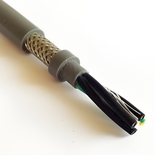
Detailed Description
Why Double-Shielded? The Limit of Single Shielding
A single copper braid shield provides 80–90% optical coverage — which sounds excellent. But at frequencies above 100 MHz (typical of VFD switching harmonics, encoder pulse edges, and wireless communication), the wavelength becomes comparable to the gaps between braid strands. At 300 MHz, the wavelength is 1 meter — and a braid gap of a few millimeters becomes a significant fraction of a wavelength, creating an effective aperture through which high-frequency EMI leaks.
This is why a single braid can adequately suppress 50 Hz motor hum but fails to protect encoder signals from VFD switching noise at 4–16 kHz with harmonics extending into the hundreds of MHz.
A foil shield solves the high-frequency problem — aluminum/polyester foil provides 100% optical coverage with zero apertures. But foil alone has a critical weakness: it fatigues quickly under repeated bending and provides almost no mechanical protection. The double-shield solution: Combine foil (inner layer, 100% coverage, high-frequency specialist) with braid (outer layer, mechanical robustness, low-frequency specialist). Each layer does what it does best.Transfer Impedance — The Number That Defines Shield Quality
Engineers evaluating shielded cable typically ask about "shielding percentage" or "coverage." These are optical metrics — how much of the surface area is covered. They tell you nothing about electrical performance.
Transfer impedance (Zₜ) is the engineering metric that matters: the ratio of voltage induced on the inner conductor to the current flowing on the shield surface, measured in mΩ/m. Lower is better.| Shield Configuration | Transfer Impedance at 30 MHz | Effective Shielding |
|---|---|---|
| Single braid (80% coverage) | ~100 mΩ/m | Baseline industrial |
| Single braid (90% coverage) | ~60 mΩ/m | Good industrial |
| Foil + drain wire only | ~200 mΩ/m (above 10 MHz, drain wire inductance dominates) | Poor above 10 MHz |
| Foil + braid (double shield) | ≤10 mΩ/m | Military/medical grade |
| Solid copper tube (reference) | ~1 mΩ/m | Rigid coax — not flexible |
The foil+braid combination achieves transfer impedance an order of magnitude below single-braid cable — and maintains this performance as the cable flexes because the outer braid protects the inner foil from mechanical damage.
Construction — Five Protective Layers
Layer 1: Inner Jacket (NBR/PVC)
Extruded buffer layer isolating the core assembly from the shield system. In a double-shielded cable, this layer is doubly critical — it must protect the foil from being abraded by the cores during bending. Unlike single-braid cables where braid-to-core abrasion takes millions of cycles to cause failure, foil can be damaged in thousands of cycles if it directly contacts moving cores.
Layer 2: Inner Shield (Al/PET Foil, 100%)
Aluminum-coated polyester foil applied metal-side-in, in contact with a tinned copper drain wire. The 100% coverage means zero apertures for high-frequency leakage. The drain wire provides a convenient single-point termination — but for full RF performance, the foil itself must be terminated 360° in the connector.
Layer 3: Intermediate Wrap (PET Tape)
Separates the inner foil from the outer braid. Without this separation layer, the braid strands can cut through the thin foil during repeated bending — destroying the high-frequency shield performance. The intermediate wrap is a wear surface that absorbs braid movement without transferring it to the foil.
Layer 4: Outer Shield (TC Braid, 90%)
Tinned copper braid providing mechanical robustness and low-frequency EMI attenuation. The braid also serves as the primary current return path — the foil is for RF shielding, not for carrying shield current. The braid is optionally bonded to the intermediate wrap with flexible adhesive to prevent telescoping under high acceleration.
Layer 5: Outer Jacket (PUR)
Full PUR outer jacket providing environmental protection. Halogen-free, oil, coolant, UV, hydrolysis, and seawater resistant. The jacket compresses the shield assembly, maintaining consistent electrical contact between foil and braid throughout flexing.
When Double-Shielded Is Necessary — Decision Criteria
| Condition | Single Shield Adequate? | Double Shield Required? |
|---|---|---|
| Motor power + encoder in same carrier, < 5 m run | ✅ Single braid (TRVVP) | ❌ Not needed |
| Motor power + encoder, > 15 m run, VFD switching > 8 kHz | ⚠️ Borderline | ✅ Foil+braid recommended |
| Encoder + Ethernet + VFD power in shared carrier | ❌ Insufficient | ✅ Required |
| Medical imaging gantry (MRI/CT) with EMI-sensitive detectors | ❌ Insufficient | ✅ Required |
| Military vehicle with MIL-STD-461 EMI compliance | ❌ Insufficient | ✅ Required |
| Semiconductor lithography stage (< 10 nm positioning) | ❌ Insufficient | ✅ Required |
| General CNC with separate power and signal carriers | ✅ Single braid | ❌ Not needed |
Shield Termination — Critical for Dual-Shield Performance
A double-shielded cable is only as good as its termination. Key requirements:
- Inner foil drain wire: Terminate at the signal-reference end only. The drain wire is for DC continuity; do not rely on it for RF performance
- Inner foil 360°: The foil must make 360° contact with the connector backshell — use a conductive gasket or spring-finger insert designed for foil shield termination
- Outer braid 360°: Fold back over EMC gland conical insert; tighten gland nut to compress braid against connector body
- Common ground point: Both shield layers must be grounded at the same physical point to avoid potential differences that create shield currents
- No pigtails: Pigtail (drain wire only) terminations create inductive stubs that nullify high-frequency shielding — regardless of how good the cable shield is. A 50 mm pigtail at 100 MHz has approximately 50 nH of inductance — equivalent to 31 Ω of impedance
Why Choose Yichi Cable Double-Jacket Double-Shielded?
- Verified transfer impedance: Every production batch of double-shielded cable is tested for Zₜ at 30 MHz using the IEC 62153-4-3 triaxial method — not calculated from braid coverage percentages
- Application-matched shield configuration: We configure the foil type, braid density, and intermediate layer based on your specific EMI environment — not a one-size-fits-all design
- Termination support: We provide application-specific termination diagrams for your connector and gland setup — because a perfect cable with poor termination is a poor system
- Full traceability: Batch-specific EMI test reports included with every shipment — essential for MIL-STD and medical device documentation
- Custom builds: Core count, cross-section, inner/outer jacket materials, shield configuration — built to your specification