Detailed Description
Control Cable vs Power Cable vs Drag Chain Cable
Industrial cables are categorized by their function. Using the wrong type leads to unnecessary cost, installation difficulty, or premature failure:
| Cable Type | Conductor Sizes | Core Count | Flexibility | Typical Use |
|---|---|---|---|---|
| Control Cable | 0.5–2.5 mm² | 2–61 cores | Good (Class 5) | PLC signals, relay wiring, sensors |
| Power Cable | 1.5–240 mm² | 2–5 cores | Moderate | Motor power, mains distribution |
| Drag Chain Cable | 0.14–35 mm² | 2–36 cores | Excellent (Class 5/6) | Continuous flex in cable carriers |
| Data Cable | 0.14–0.34 mm² | 2–40 pairs | Good | RS-485, CAN, Ethernet, fieldbus |
Flex Control Cable occupies the signal wiring domain — it carries control signals (0–10 V, 4–20 mA, 24 V DC, 230 V AC relay coils), not motor power. The conductor geometry is optimized for high core counts and easy termination, not for millions of flex cycles.
Core Identification — Reading the Numbers
Control cables connect dozens of signal points between cabinets and field devices. Correct core identification is not optional — a wiring error on a 50-core cable can take hours to diagnose.
Numbered Black Cores (VDE 0293 Standard)
- All cores are black with white ink-jet printed numbers: 1, 2, 3, ...
- Green-yellow protective conductor (marked or separate) — mandatory from 3 cores upward
- Numbers are printed continuously along the core length — readable at any cut point
- Advantage: Works for any core count — 2 to 61+ with no practical limit
- Disadvantage: Numbers can be harder to read than distinct colors in poor lighting
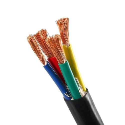
Color Coded (DIN 47100)
- Cores have distinct colors following a standard sequence: white, brown, green, yellow, gray, pink, blue, red, black, violet...
- Above 10 cores, colors repeat with stripe or ring differentiation
- Up to 61 uniquely identifiable color combinations
- Advantage: Instant visual identification — faster wiring than reading numbers
- Disadvantage: Limited to 61 colors; above this, must switch to numbered system
Cross-Section Selection for Control Signals
Control signals carry very little current — typically < 1 A for PLC inputs and < 0.5 A for analog signals. The conductor size is determined by mechanical robustness and voltage drop on long runs, not by current-carrying capacity:
| Cross-Section | Typical Use | Current Capacity | Max Run Length (24 V DC)* |
|---|---|---|---|
| 0.5 mm² | PLC digital inputs, pushbuttons, limit switches | 3 A | 100 m |
| 0.75 mm² | PLC digital outputs (up to 2 A), solenoid valves | 6 A | 150 m |
| 1.0 mm² | Relay coils, contactor coils (230 V AC) | 10 A | 200 m |
| 1.5 mm² | Analog 4–20 mA loops (long runs), small motors | 16 A | 300 m |
| 2.5 mm² | Control transformer secondary distribution | 25 A | 500 m |
*Maximum run length at < 5% voltage drop with full load current. Longer runs may require larger sections.
Shielded Control Cable — When to Specify
Standard unshielded control cable is adequate for most factory environments. Add shielding when:
- Analog signals (4–20 mA, 0–10 V) run parallel to unshielded power cables for > 5 m
- Encoder or pulse signals share a cable tray with VFD motor cables
- Long runs (> 50 m) through areas with unknown EMI sources
- The machine is exported to markets with stricter EMC regulations (EU CE marking requires EMC compliance under 2014/30/EU)
Installation — Control Cable in Cable Trays and Conduit
- Separation from power: Minimum 200 mm separation from unshielded power cables in parallel runs. Cross at 90° when crossing power cable paths
- Conduit fill: ≤ 40% of conduit cross-section for easy pulling. Over-filled conduits damage the jacket during installation
- Cold-weather installation: Below +5°C, PVC stiffens. Warm the cable to at least +10°C before pulling — a cold cable pulled through conduit can stretch and thin the insulation
- Service loops: Leave 300–500 mm of extra cable at each termination point inside the cabinet. Do not "stretch" the cable to reach a terminal — tension on the terminations causes intermittent faults
- Labeling: Label both ends of each multi-core cable with the cable number, source cabinet, and destination. A P-touch label now saves an hour of wire tracing later
Why Choose Yichi Cable Flex Control?
- Full configuration range: 2–61 cores, 0.5–2.5 mm² from stock — no minimum order for standard configurations
- Dual identification availability: Numbered or color coded — your choice, from stock, not a special order
- Consistent numbering: Our numbered cores are ink-jet printed, not hot-stamped. Hot stamping can damage thin insulation; ink-jet printing is non-contact and leaves the insulation intact
- Cut-to-length: Order exact meter lengths — no waste, no splicing
- Shielded variants in stock: Standard configurations with overall braid shield — for when control signals must coexist with power cables