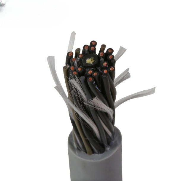
Detailed Description
What Makes a Cable "High-Speed"?
Standard drag chain cable is rated for 3–5 m/s travel. At these speeds, the dominant mechanical stress on the cable is bending fatigue — the repeated flexing as the cable passes through the carrier's bend radius.
At 10 m/s — twice the speed — the physics changes. Three additional forces become significant:
1. Inertial Shock
When a cable traveling at 10 m/s reverses direction (typical in reciprocating sorters and shuttle systems), the deceleration imposes a longitudinal shock wave along the cable. At 50 m/s² acceleration, a 1 kg cable experiences 50 N of longitudinal force — equal to hanging a 5 kg weight from the cable, applied and reversed multiple times per second. Standard drag chain cables lack the tensile reinforcement to survive this.
2. Internal Core Migration
At high acceleration, the cable's individual insulated cores experience significant inertial forces relative to each other. In a standard cable with dditionally long lay lengths, cores can migrate longitudinally through the cable structure — a phenomenon known as "corkscrewing" or "worming." Once a core shifts, it creates a localized stress concentration that leads to rapid fatigue failure.
3. Carrier Wall Friction Heating
At 10 m/s, the cable's outer jacket rubs against the carrier walls at significantly higher velocity. Frictional heating can raise the jacket temperature 10–15°C above ambient. Standard PVC jackets soften at elevated temperature, increasing friction in a runaway feedback loop.
Engineering a High-Speed Cable — Four Key Design Elements
1. PP Core Insulation — Friction Starts Inside
PP (polypropylene) has a coefficient of friction approximately 40–50% lower than PVC. In a standard cable at moderate speed, internal core-to-core friction is minor. At 10 m/s with rapid acceleration, internal friction becomes the dominant heat source inside the cable. PP insulation eliminates this.
2. Ultra-Short Lay Length — Preventing Core Migration
High-speed cables use lay lengths 20–30% shorter than standard drag chain cables. A shorter lay length means each core completes its spiral path in a shorter distance, mechanically locking it in place relative to its neighbors. This prevents the longitudinal core migration that acceleration forces would otherwise cause.
3. Kevlar Tensile Elements — Absorbing Acceleration Shock
Unlike standard cables where tensile fillers are optional, high-speed cables include Kevlar (aramid) or high-tenacity PET tensile elements as a design requirement, not an option. These fibers are embedded in the core assembly and absorb the longitudinal shock of rapid acceleration and deceleration, preventing the copper conductors from experiencing direct tensile stress.
4. Low-Adhesion Outer Jacket — Reducing Carrier Drag
TPE (thermoplastic elastomer) or PUR jackets are specified rather than PVC. Beyond their environmental resistance, these materials have inherently lower surface adhesion — they "glide" against carrier walls rather than gripping. This reduces the friction force the cable's own drive system must overcome, and reduces friction heating at speed.
Travel Speed, Distance, and Flex Life — The Trade-off Triangle
No cable is optimal at maximum speed, maximum distance, and maximum flex life simultaneously. Each application prioritizes two of the three:
| Priority | Speed | Distance | Flex Life | Typical Application |
|---|---|---|---|---|
| Speed + Distance | 10 m/s | 100 m | 5M cycles | Parcel sorter, AS/RS long travel |
| Speed + Life | 10 m/s | < 30 m | 12M cycles | Semiconductor wafer handler, pick-and-place |
| Distance + Life | 5 m/s | 100–400 m | 10M cycles | Overhead crane, gantry, long-stroke machine tool |
Our engineering team helps you select the right balance based on your actual operating parameters — not generic ratings.
Temperature Management at Speed
Continuous operation at 10 m/s generates measurable frictional heating. Design allowances:
- ≤ 5 m/s: No temperature derating needed — standard temperature ratings apply
- 5–7.5 m/s: Allow 5°C ambient margin above the cable's rated temperature
- 7.5–10 m/s: Allow 10°C ambient margin; consider forced-air carrier ventilation
- > 10 m/s continuously: Contact our engineering team for thermal analysis
Installation for High-Speed Carriers
- Carrier type: Use low-friction carriers with smooth interior surfaces. Avoid ribbed carriers — at 10 m/s, ribs create vibration and localized wear
- Fill ratio: Reduce to ≤ 50% of carrier cross-section (vs 60% standard). The extra space prevents the cable from making continuous wall contact that causes friction heating at speed
- Single layer only: Never stack cables in a high-speed carrier. Stacked cables compress under their own weight at high acceleration, crushing the bottom cable
- Strain relief: Double-clamp both ends with rubber-lined clamps. At 10 m/s and 100 m/s², a loose clamp is a failure point within hours
- Pre-tension: Apply slight pre-tension (0.5–1% of cable length) during installation. This prevents the cable from forming loose loops that slap against carrier walls at speed
- Break-in period: Run the cable at 50% speed for the first 100 cycles. This allows the PP insulation layers to polish against each other, reducing future internal friction
Why Choose Yichi Cable High-Speed?
- Application-specific engineering: We do not sell a single "high-speed" cable. We configure lay length, tensile fillers, and jacket material based on your actual speed, acceleration, and travel distance
- Vibration analysis available: For speeds above 7.5 m/s on long-stroke carriers, we can model the cable's natural frequency to avoid resonance with the carrier's motion profile
- Pre-tested at speed: New high-speed designs are tested on a 10 m/s reciprocating test rig in our CNAS-accredited lab before customer shipment
- Global certifications: UL/CSA for North America, CE/DESINA/NFPA 79 for Europe — one cable meets multiple regional requirements