Detailed Description
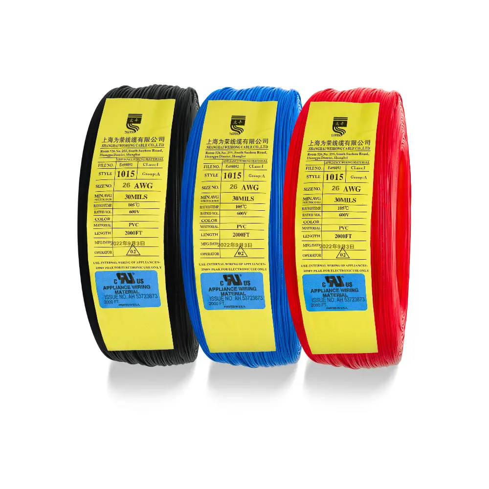
UL1015 hookup wire is a single-conductor, 600 V, 105 °C appliance wiring material built for internal equipment wiring where a UL-recognized hook-up wire is required. It uses a lead-free tinned oxygen-free copper conductor and PVC insulation, and it is available from 30 AWG to 4/0 AWG. This page focuses on the UL1015 construction itself, not on a multi-standard general-purpose wire range.
What the UL1015 Hookup Wire Is and Where It Fits
UL1015 hookup wire is intended for fixed internal wiring in equipment, not for continuous flexing unless the equipment builder confirms suitability. Typical uses include lighting fixtures, appliance harnesses, control panels, industrial control equipment, robotics, automotive internal wiring, electronic devices, power supplies, and power equipment. The construction is single-conductor, so it is used where individual point-to-point connections, panel wiring, or harness branches need a 600 V, 105 °C rated lead.
The cable solves a common OEM and panel-builder problem: selecting a wire that matches the voltage and temperature limits of the equipment while carrying the required UL marking and flame performance. Because the wire surface is printed with product name, temperature rating, voltage rating, UL certification number, and VW-1, it can be inspected and traced after installation.
Construction and Key Ratings
The conductor is lead-free tinned oxygen-free copper, stranded for flexibility and mechanical strength. Tinning resists oxidation and corrosion, keeps resistance low, and makes soldering easier after storage. The stranded design also increases tensile strength and helps the copper strands stay together when the wire is cut or stripped.
The insulation is PVC made from virgin compound, not recycled material. This supports consistent wall thickness and low eccentricity, which reduces the risk of electrical breakdown. The insulation is not a jacket over a shielded core; this is a single-conductor construction. Surface marking is clear enough for field acceptance and batch traceability.
| Parameter | Value |
|---|---|
| Voltage rating | 600 V |
| Temperature rating | 105 °C |
| Flame rating | VW-1; FT1 vertical burn test |
| Certification | UL, with UL certification number marked on the wire |
| Environmental compliance | RoHS and REACH |
| Conductor | Lead-free tinned oxygen-free copper, stranded |
| Insulation | PVC, virgin compound, no recycled material |
| Configuration | Single conductor |
| AWG range | 30 AWG to 4/0 AWG |
| Standard colors | 12 standard colors plus bi-color |
| Surface marking | Product name, temperature rating, voltage rating, UL certification number, VW-1 |
| Supply | Cut to length by the meter from standard coils |
Conductor and Insulation Specifications
Table 1 lists conductor construction, insulation thickness, nominal outer diameter, and 20 °C maximum conductor resistance across the full AWG range.
| AWG | Cross-section mm² | Conductor construction NO./mm | Conductor diameter mm | Nominal insulation thickness mm | Nominal insulation O.D. mm | 20 °C max conductor resistance (Ω/km) |
|---|---|---|---|---|---|---|
| 30 | — | 7/0.10 | 0.30 | 0.79 | 1.88 | 354.24 |
| 28 | — | 7/0.127 | 0.38 | 0.79 | 1.96 | 223.75 |
| 26 | 0.14 | 7/0.16 | 0.48 | 0.79 | 2.06 | 139.73 |
| 24 | 0.22 | 11/0.16 | 0.61 | 0.79 | 2.19 | 93.30 |
| 22 | 0.34 | 17/0.16 | 0.76 | 0.79 | 2.34 | 55.00 |
| 20 | 0.52 | 26/0.16 | 0.94 | 0.79 | 2.52 | 34.60 |
| 18 | 0.82 | 41/0.16 | 1.18 | 0.79 | 2.76 | 21.80 |
| 16 | 1.32 | 26/0.254 | 1.49 | 0.79 | 3.07 | 13.70 |
| 14 | 2.08 | 41/0.254 | 1.88 | 0.79 | 3.46 | 8.62 |
| 12 | 3.29 | 65/0.254 | 2.37 | 0.79 | 3.95 | 5.43 |
| 10 | 5.32 | 105/0.254 | 3.40 | 0.79 | 4.98 | 3.41 |
| 8 | 8.51 | 168/0.254 | 4.31 | 1.15 | 6.60 | 2.16 |
| 6 | 13.47 | 266/0.254 | 5.43 | 1.52 | 8.50 | 1.39 |
| 4 | 21.37 | 420/0.254 | 6.78 | 1.52 | 9.80 | 0.88 |
| 2 | 33.63 | 665/0.254 | 9.04 | 1.52 | 12.10 | 0.55 |
| 1 | 41.73 | 824/0.254 | 9.80 | 1.52 | 13.70 | 0.44 |
| 1/0 | 52.90 | 1045/0.254 | 10.86 | 2.05 | 15.00 | 0.35 |
| 2/0 | 67.40 | 627/0.37 | 12.30 | 2.05 | 16.80 | 0.28 |
| 3/0 | 83.70 | 779/0.37 | 13.80 | 2.05 | 17.80 | 0.22 |
| 4/0 | 107.20 | 988/0.37 | 15.40 | 2.05 | 19.60 | 0.17 |
Notes for Table 1:
- Conductor resistance is stated at 20 °C.
- The 30 AWG and 28 AWG rows do not list a cross-sectional area, so those cells are shown as —.
| AWG | Standard length |
|---|---|
| 26 | 2000 Ft (610 m) |
| 16 | 1000 Ft (305 m) |
| 8 | 656 Ft (200 m) |
| 4 | 328 Ft (100 m) |
| 1/0 | 164 Ft (50 m) |
Other sizes are supplied cut to length by the meter from standard coils.
Overall Diameter and Reference Current-Carrying Capacity
Table 2 lists overall outer diameter and reference current-carrying capacity. The current values are reference figures for comparison and are not presented as IEC or UL standard ampacity ratings.
| AWG | Overall O.D. (mm) (±0.01 mm) | Conductor construction | Cross-section mm² | Reference current-carrying capacity (A) |
|---|---|---|---|---|
| 24 | 2.20 | 11/0.16TS | 0.22 | 2.7 |
| 22 | 2.40 | 17/0.16TS | 0.34 | 4.1 |
| 20 | 2.55 | 21/0.178TS | 0.52 | 6.3 |
| 18 | 2.80 | 34/0.178TS | 0.85 | 9.3 |
| 16 | 3.10 | 26/0.254TS | 1.32 | 13.2 |
| 14 | 3.50 | 41/0.254TS | 2.08 | 16.6 |
| 12 | 3.90 | 65/0.254TS | 3.29 | 26.3 |
| 10 | 5.10 | 105/0.254TS | 5.32 | 43 |
| 8 | 6.60 | 165/0.254TS | 8.36 | 67 |
| 7 | 7.50 | 208/0.254TS | 10.54 | 84 |
| 6 | 8.50 | 263/0.254TS | 13.33 | 107 |
| 5 | 9.50 | 237/0.30TS | 16.75 | 134 |
| 4 | 10.2 | 300/0.30TS | 21.21 | 170 |
| 3 | 10.7 | 360/0.30TS | 25.45 | 204 |
| 2 | 11.7 | 476/0.30TS | 33.65 | 269 |
VW-1 Flame Test and Compliance
The VW-1 test is a vertical burn test. The specimen is held vertically. A test burner with a 125 mm flame and 500 W thermal power is applied for 15 seconds, then removed for 15 seconds. This cycle is repeated five times. The pass criteria are: afterflame must not exceed 60 seconds; the specimen must not lose more than 25% of its material; and surgical cotton placed below must not be ignited by falling material.
UL1015 hookup wire carries UL certification, and the wire surface is printed with the UL certification number along with the product name, temperature rating, voltage rating, and VW-1. FT1 vertical burn performance and REACH compliance are also listed for this construction.
Selection, Installation, and Available Configurations
For selection, confirm the equipment voltage does not exceed 600 V and the operating temperature does not exceed 105 °C. Choose the AWG from Table 1 and Table 2 according to conductor resistance, outer diameter, and reference current-carrying capacity. The wire is available from 30 AWG to 4/0 AWG in 12 standard colors plus bi-color, which helps separate circuits in panels and harnesses.
During installation, the stranded tinned copper conductor is designed to be cut and stripped without the strands fanning out easily, and the tinned surface supports soldering. Set the bend radius according to the equipment manufacturer's requirements. Standard lengths cover 26 AWG, 16 AWG, 8 AWG, 4 AWG, and 1/0 AWG. Other sizes are supplied cut to length by the meter from standard coils.
For OEM electrical design engineers and panel builders, the practical value is the combination of published UL marking, 600 V and 105 °C ratings, VW-1 flame performance, and a full AWG table from 30 AWG to 4/0 AWG. This lets you verify conductor size, insulation thickness, outer diameter, and reference current capacity before routing the wire into lighting fixtures, appliance harnesses, control panels, industrial control equipment, robotics, automotive internal wiring, electronic devices, power supplies, and power equipment.
To confirm a UL1015 hookup wire size for your equipment, send the required AWG, color, length, voltage, and temperature conditions through the inquiry form.