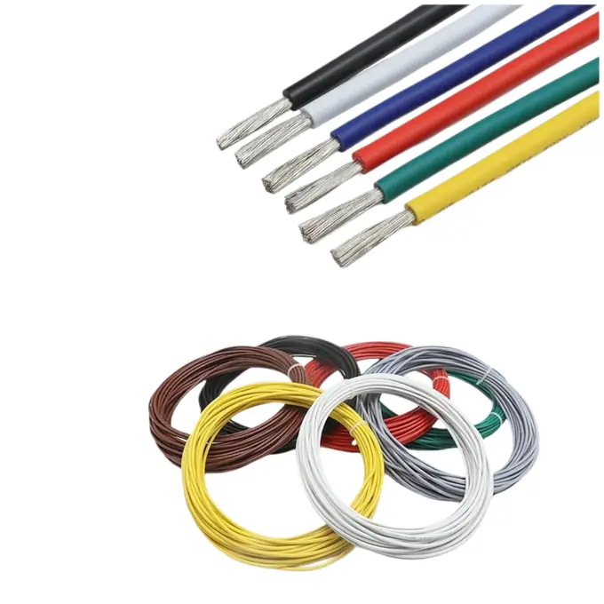
Detailed Description
- q: "What is the certification status of this wire?"
- q: "How is the wire packed, and can I get a short length for a prototype?"
a: "Standard packing is 610 m per roll for 30–20 AWG, 305 m per roll for 18–12 AWG, and 100 m per roll for 11–10 AWG. Shorter packs of 8 m and 32 m are also available, which covers prototype and sample builds."
What Is UL1332 FEP High Temperature Wire?
UL1332 FEP high temperature wire is a single-conductor hookup wire with a stranded tinned copper conductor and fluorinated ethylene propylene (FEP) insulation. It carries a 200 °C continuous temperature rating, a 300 V voltage rating, and a VW-1 flame rating, and it is supplied in sizes from 30 AWG to 10 AWG.
The jacket is printed AWM1332 **AWG 200°C 300V VW-1 FEP on one line and AWM I A/B 200°C 300V FT1 on another, so the AWM style, temperature, voltage, and flame rating can be read directly off the wire. This matters when an inspector or a customer's quality team checks a harness against the drawing.
It is used where a standard PVC hookup wire would not survive: inside heated appliances, around LED drivers and lamp housings, on temperature sensor leads, and in equipment enclosures where a 105 °C rated lead would harden or crack over time. The FEP wall also resists acids, alkalis, oil, water, and moisture, which matters in appliances that see steam, condensate, or cooking grease.
Construction: Tinned Copper Conductor and FEP Insulation
The conductor is stranded tinned copper. The supplier also lists lead-free tinned copper and tinned oxygen-free copper as material options. Tinning protects the copper from oxidation before and after assembly, and it makes the strands take solder quickly during termination. The strands are laid up at high density so the conductor holds its shape when the insulation is stripped — the strands do not fan out and need less re-twisting before a crimp or a solder joint.
The insulation is FEP, a fluoroplastic also known as Teflon in the trade. This product uses an NP-grade FEP compound that meets RoHS and NP environmental requirements. FEP is a thermoplastic, so the wall can be extruded smoothly and concentrically. A concentric wall with a low eccentricity rate keeps the conductor centered, which reduces the chance of a thin spot that could lead to a current breakdown. The surface is smooth and even in thickness, which helps automated stripping tools cut cleanly.
FEP and silicone insulation are not interchangeable. Silicone rubber stays more flexible and is often the better choice where a lead is repeatedly flexed by hand. FEP has better chemical and moisture resistance, a smoother surface, and a smaller outside diameter for the same conductor, and it strips without fraying the strands — which is why it is common in precision electronic assemblies. For applications that need a 600 V rating, a different insulation and wall thickness are required; a 300 V FEP lead is not the right part for that circuit.
UL1332 Specifications and Ratings
The table below collects the electrical and environmental ratings that apply across the size range. Values that vary by AWG are in the specification tables further down.
| Parameter | Value |
|---|---|
| Rated temperature | 200 °C |
| Low temperature rating | −60 °C |
| Rated voltage | 300 V |
| Flame rating | VW-1 / FT1 |
| Dielectric withstand | 2000 V AC per minute |
| OD tolerance | ±0.2 mm |
| Conductor | Tinned copper, stranded |
| Insulation | FEP (fluorinated ethylene propylene) |
| Certification | UL (AWM style 1332) |
| Environmental | RoHS / NP compliant |
UL1332 Specification Tables
The three tables below are quoted as given in the supplier's specification sheets. The main table covers the full 30 AWG to 10 AWG range with overall diameter, cross-section, temperature, voltage, and packing. The two following tables add conductor resistance, safety current, wall thickness, and per-AWG construction options.
Main Specification Table
| AWG | Stranding | Overall OD (mm) | Cross-Section (mm²) | Temperature (°C) | Rated Voltage (V) | Packing |
|---|---|---|---|---|---|---|
| 30 AWG | 7/0.10TS | 0.65 | 0.05 | 200 | 300 | 610 m/roll |
| 28 AWG | 7/0.12TS | 1.08 | 0.08 | 200 | 300 | 610 m/roll |
| 26 AWG | 7/0.16TS | 1.10 | 0.14 | 200 | 300 | 610 m/roll |
| 24 AWG | 7/0.20TS | 1.21 | 0.22 | 200 | 300 | 610 m/roll |
| 22 AWG | 19/0.14TS | 1.36 | 0.30 | 200 | 300 | 610 m/roll |
| 20 AWG | 19/0.18TS | 1.57 | 0.50 | 200 | 300 | 610 m/roll |
| 18 AWG | 19/0.225TS | 1.78 | 0.76 | 200 | 300 | 305 m/roll |
| 16 AWG | 19/0.30TS | 2.16 | 1.34 | 200 | 300 | 305 m/roll |
| 14 AWG | 19/0.37TS | 2.50 | 2.04 | 200 | 300 | 305 m/roll |
| 13 AWG | 19/0.41TS | 2.71 | 2.51 | 200 | 300 | 305 m/roll |
| 12 AWG | 19/0.45TS | 3.00 | 3.02 | 200 | 300 | 305 m/roll |
| 11 AWG | 37/0.37TS | 3.30 | 3.98 | 200 | 300 | 100 m/roll |
| 10 AWG | 37/0.45TS | 3.73 | 5.88 | 200 | 300 | 100 m/roll |
Values are quoted as given in the supplier's specification tables. The supplier notes that data are for reference and carry some tolerance; current values are limits, so allow a 20% margin.
Table B — Conductor Resistance and Safety Current (30 AWG–14 AWG)
| AWG | Stranding | Conductor OD (mm) | Nominal Cross-Section (mm²) | Average Wall (mm) | Overall OD (mm) | Conductor Resistance (Ω/km @ 20 °C) | Safety Current (A @ 30 °C) |
|---|---|---|---|---|---|---|---|
| 30 AWG | 7/0.10TS | 0.31 | 0.050 | 0.33 | 0.6 | 316 | 0.66 |
| 28 AWG | 7/0.12TS | 0.37 | 0.090 | 0.33 | 0.8 | 196 | 1.06 |
| 26 AWG | 7/0.16TS | 0.49 | 0.14 | 0.33 | 1.1 | 124 | 1.69 |
| 24 AWG | 7/0.20TS | 0.61 | 0.22 | 0.33 | 1.2 | 79 | 2.20 |
| 22 AWG | 19/0.15TS | 0.76 | 0.34 | 0.33 | 1.35 | 52 | 3.36 |
| 20 AWG | 19/0.18TS | 0.91 | 0.54 | 0.33 | 1.50 | 32 | 5.39 |
| 18 AWG | 19/0.23TS | 1.16 | 0.82 | 0.33 | 1.75 | 21 | 8.24 |
| 16 AWG | 19/0.30TS | 1.51 | 1.34 | 0.33 | 2.1 | 13 | 13.4 |
| 14 AWG | 19/0.37TS | 1.86 | 2.04 | 0.33 | 2.55 | 8.52 | 20.4 |
Dielectric withstand test (AC V/min): 2000. Values are quoted as given in the supplier's specification tables.
Table C — Construction, Insulation Thickness, and Maximum Conductor Resistance
| AWG | Conductor Construction | Type | Conductor Diameter (mm) | Insulation Thickness (mm) | Overall OD (mm) | Max Conductor Resistance (Ω/km) | Packing m (ft) |
|---|---|---|---|---|---|---|---|
| 30 | 1/0.26 | Solid | 0.26 | 0.305 | 0.87 | 361 | 610 (2000) |
| 30 | 7/0.10 | Stranded | 0.30 | 0.305 | 0.91 | 361 | 610 (2000) |
| 28 | 1/0.32 | Solid | 0.32 | 0.305 | 0.93 | 227 | 610 (2000) |
| 28 | 7/0.12 | Stranded | 0.36 | 0.305 | 0.97 | 227 | 610 (2000) |
| 26 | 7/0.16 | Stranded | 0.48 | 0.305 | 1.09 | 143 | 610 (2000) |
| 26 | 19/0.10 | Stranded | 0.48 | 0.305 | 1.11 | 143 | 610 (2000) |
| 24 | 1/0.50 | Solid | 0.50 | 0.305 | 1.11 | 89.3 | 610 (2000) |
| 24 | 7/0.20 | Stranded | 0.60 | 0.305 | 1.21 | 89.3 | 610 (2000) |
| 24 | 19/0.12 | Stranded | 0.60 | 0.305 | 1.21 | 89.3 | 610 (2000) |
| 22 | 1/0.65 | Solid | 0.65 | 0.33 | 1.31 | 56.4 | 305 (1000) |
| 22 | 7/0.254 | Stranded | 0.76 | 0.33 | 1.42 | 56.4 | 305 (1000) |
| 22 | 19/0.15 | Stranded | 0.75 | 0.33 | 1.41 | 56.4 | 305 (1000) |
| 20 | 1/0.81 | Solid | 0.81 | 0.33 | 1.47 | 35.2 | 305 (1000) |
| 20 | 7/0.31 | Stranded | 0.93 | 0.33 | 1.59 | 35.2 | 305 (1000) |
| 20 | 19/0.19 | Stranded | 0.93 | 0.33 | 1.59 | 35.2 | 305 (1000) |
| 18 | 1/1.02 | Solid | 1.02 | 0.33 | 1.68 | 22.2 | 305 (1000) |
| 18 | 7/0.39 | Stranded | 1.17 | 0.33 | 1.83 | 22.2 | 305 (1000) |
| 18 | 19/0.235 | Stranded | 1.17 | 0.33 | 1.83 | 22.2 | 305 (1000) |
| 16 | 1/1.30 | Solid | 1.30 | 0.33 | 1.96 | 14 | 305 (1000) |
| 16 | 7/0.49 | Stranded | 1.47 | 0.33 | 2.13 | 14 | 305 (1000) |
| 16 | 19/0.30 | Stranded | 1.50 | 0.33 | 2.16 | 14 | 305 (1000) |
| 14 | 19/0.37 | Stranded | 1.85 | 0.33 | 2.51 | 8.78 | 305 (1000) |
| 12 | 19/0.47 | Stranded | 2.35 | 0.33 | 3.01 | 5.53 | 305 (1000) |
| 10 | 19/0.61 | Stranded | 3.05 | 0.33 | 3.71 | 3.476 | 305 (1000) |
Values are quoted as given in the supplier's specification tables.
Where This FEP Hookup Wire Is Used
This wire is specified at the equipment level, not at the "industry" level. Typical points of use:
- PCB and circuit board connection leads in LED luminaires, lamp drivers, and decorative lighting.
- Internal wiring of household appliances: air conditioners, microwave ovens, electronic sterilizers, rice cookers, electric kettles, space heaters, electric ovens, and electric frying pans.
- Temperature sensor and thermal probe lead wire, where the lead runs close to the heated zone.
- Electronic transformer, motor, and computer peripheral internal connections.
- Smart home, security, and medical equipment harnesses that need a flame-retardant, low-smoke lead.
- Automotive instrument and automotive electronics wiring exposed to engine-bay heat.
- Electric toys and mechanical instruments where a small outside diameter and a smooth jacket help routing.
Selection and Installation Notes
Choose the AWG from the current the circuit will carry, then check that the overall diameter fits the connector, the grommet, and the bend path. Table B lists a safety current at 30 °C; the supplier states these are limit values and recommends allowing a 20% margin. If the lead runs in a bundle or inside a heated enclosure, the margin should be larger.
Stripping FEP takes a sharp blade and a light touch. The insulation is harder than PVC, so a tool set for PVC will usually cut too deep. The high-density stranded conductor holds its lay after stripping, which reduces re-twisting before crimping. Tinned strands solder quickly without extra flux in most cases. Because FEP has a low friction surface, some cable ties and adhesives do not grip it well — use a mechanical clamp or a tie with a rubber-lined saddle where the lead must be fixed.
FEP is stiffer than silicone rubber. In a static route inside an enclosure that is not a problem, and the smaller diameter often lets the lead fit where silicone would not. In a route that is flexed repeatedly by hand or by a moving door, silicone is usually the better choice. For high-vibration routes, support the lead near the termination so the strand bundle does not work-hardened at the crimp.
Certification, Colors, Packaging, and Custom Options
The wire is a UL AWM style 1332 product. The jacket carries the VW-1 and FT1 flame markings and the 200 °C / 300 V ratings. The compound meets RoHS and NP environmental requirements. The UL file number is not part of the current specification set; request it from the factory if your documentation package requires the E-number.
Colors available include white, black, red, brown, yellow, blue, green, yellow-green, transparent, orange, purple, grey, pink, and yellow with a green stripe. More than ten colors are stocked, which is enough to identify circuits in a multi-lead harness without adding markers.
Standard packing is 610 m per roll for 30–20 AWG, 305 m per roll for 18–12 AWG, and 100 m per roll for 11–10 AWG. Shorter packs (8 m, 32 m) are also available for prototype and sample builds. Custom specifications and colors can be produced to order.
To check whether this UL1332 FEP high temperature wire fits your equipment, send the required AWG, color, packing length, and the operating temperature and voltage of the circuit. The form on this page goes straight to the factory, and the reply will confirm the closest standard construction or a custom build.