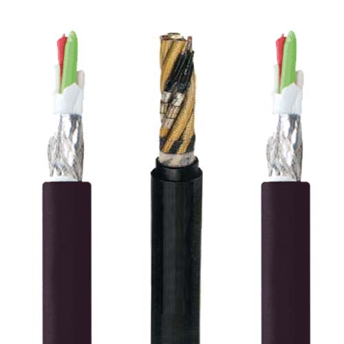
Detailed Description
Why Signal Cables Need Their Own Festoon Product
A festoon system cable carrying 3-phase motor power can tolerate a certain amount of electrical noise. The motor does not care if 50 mV of induced voltage appears on the phase conductor — it is invisible against the 400 V operating voltage. But a load cell signal is 0–20 mV full scale. A PT100 temperature sensor changes resistance by 0.385 Ω per degree Celsius. An RS-485 differential signal operates at ±1.5 V minimum. These signals cannot tolerate noise from adjacent power conductors.
The festoon signal cable addresses this through three design elements that a general-purpose festoon cable does not have:
1. Twisted Pair Construction
Each signal circuit is formed by two conductors twisted together at a defined lay length (typically 30–50 mm per twist). When an external magnetic field — from an adjacent power conductor carrying 50 A at 50 Hz — impinges on the twisted pair, the induced voltage is equal in both conductors because they occupy, on average, the same position in the magnetic field. A differential receiver at the end of the pair sees only the difference between the two conductors — the induced common-mode voltage is cancelled. This is why twisted pairs are the foundation of all industrial signal transmission: 4–20 mA analog loops, RS-485, CAN bus, encoder signals, and thermocouple circuits.
2. Individual Pair Shielding
The twisted pair alone cancels magnetically induced common-mode noise. But it does not cancel capacitively coupled noise — high-frequency interference from VFD switching (2–16 kHz carrier frequency, with harmonics into the MHz range) couples through the parasitic capacitance between the power conductor and the signal conductor. An aluminium/polyester foil wrapped around each individual pair creates a Faraday cage — the capacitively coupled noise current flows in the foil to ground via the drain wire, not in the signal conductor.
3. PE/PP Insulation (Not PVC)
PVC has a dielectric constant of approximately 4–6. PE and PP have dielectric constants of 2.3–2.4. Lower dielectric constant means lower capacitance per meter of cable, which means less signal attenuation over long festoon runs. For a 100-meter RS-485 run at 1 MHz, the difference between PVC insulation (120 pF/m) and PE insulation (50 pF/m) is the difference between a clean signal and a severely attenuated one.
Signal Types and Pair Requirements
| Signal Type | Voltage / Current Level | Pair Configuration | Shield Requirement | Typical Run Length |
|---|---|---|---|---|
| Limit switch (dry contact) | 24 V DC / 10–100 mA | 1 pair per switch | Foil shield sufficient | 10–50 m |
| 4–20 mA analog (load cell, pressure) | 4–20 mA DC | 1 pair | Individual foil + overall braid | 20–100 m |
| PT100 RTD (3-wire) | mV-level | 1 pair + 1 single core | Individual foil + overall braid | 10–50 m |
| Incremental encoder (A/B/Z) | 5–24 V DC, up to 500 kHz | 3–4 pairs | Individual foil per pair + overall braid | 10–30 m |
| RS-485 / Modbus RTU | ±1.5 V differential | 1 pair + signal ground | Individual foil + overall braid | Up to 1 200 m at 100 kbps |
| CAN bus | ±1.5 V differential | 1 pair (120 Ω characteristic impedance) | Individual foil + overall braid | 40 m at 1 Mbps |
| VFD 0–10 V speed reference | 0–10 V DC | 1 pair | Individual foil + overall braid | 10–30 m |
For encoder signals running alongside VFD motor cables in the same festoon loop, the overall tinned copper braid shield is essential — it provides low-impedance grounding for high-frequency VFD switching noise that the foil shield alone cannot handle effectively.
Yichi Festoon Signal Cable — Shield Quality
- Foil coverage verified: Each production batch is sampled and the foil wrap is inspected under magnification — 100% coverage with minimum 25% overlap is the acceptance criterion. Gaps in foil coverage create leakage paths for capacitively coupled noise
- Braid coverage measured: Tinned copper braid coverage is optically measured on production samples — ≥85% is the acceptance criterion. Braid angle is controlled to 30–45° from the cable axis for optimal coverage-to-flexibility ratio
- Drain wire continuity tested: The drain wire in each individually shielded pair is continuity-tested during production — an open drain wire renders the foil shield electrically floating and ineffective
- Capacitance measured per pair: Capacitance (core-to-core and core-to-shield) is measured at 800 Hz on every production length — values exceeding the specification trigger rejection. This is the single most important electrical test for a signal cable