Detailed Description
What Is a Shielded Control Cable?
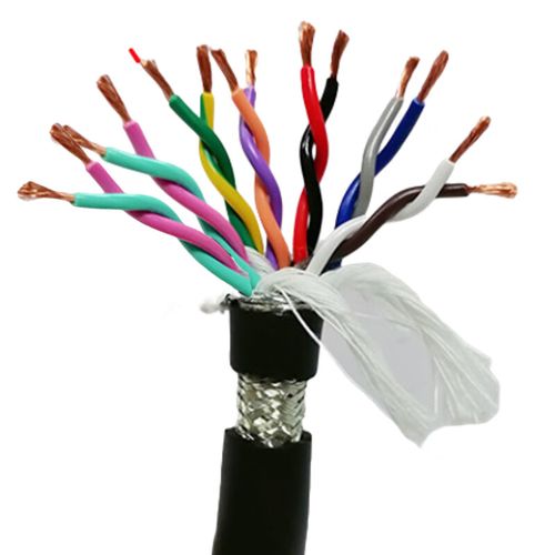
A shielded control cable is a multi-core cable with an overall electromagnetic shield, engineered to carry switching-level control signals — relay coil energizing currents, contactor commands, solenoid valve actuation, indicator lamp power — in industrial environments where unshielded cables risk false triggering from nearby power and VFD cables.
Control circuits operate at higher voltages and currents than sensor and instrumentation circuits:
- 24 V DC control — the workhorse of PLC digital outputs, driving relay coils (typically 30–100 mA at 24 V DC) and small solenoid valves
- 110/230 V AC control — common in legacy machinery and building automation, powering contactor coils, larger solenoid valves, and motor starter circuits directly
Shielded Control Cable vs Industrial Shielded Cable — Different Cables for Different Circuits
| Parameter | Shielded Control Cable | Industrial Shielded Cable |
|---|---|---|
| Primary application | Relay coils, contactors, solenoid valves, indicator lamps (switching circuits) | Sensor signals, 4–20 mA, RS-485, digital I/O (measurement and data circuits) |
| Conductor cross-section | 0.5–2.5 mm² — sized for control circuit current | 0.14–2.5 mm² — 0.14/0.22 mm² common for signal |
| Insulation type | PVC standard (70°C rating sufficient) | PVC standard, PE optional for low capacitance |
| Capacitance critical? | No — control circuits switch slowly (Hz to tens of Hz) | Yes — especially for analog and high-speed digital |
| Typical core count | 2–24 (practical for relay/actuator wiring) | 2–37 (higher counts for sensor consolidation) |
| Voltage drop concern | Yes — sized per current and cable length | Not for signal (voltage drop negligible at mA-level current) |
The two cables look similar — both have an overall braid shield — but they are specified for different electrical loads. Choosing a signal cable for a control circuit risks excessive voltage drop (undersized conductors). Choosing a control cable for a sensor circuit misses the low-capacitance PE insulation that preserves signal quality.
Conductor Sizing for Control Circuits — Why Cross-Section Matters
In a sensor circuit at 4–20 mA, a 0.22 mm² conductor with 84 Ω/km resistance drops 1.7 V over 100 m — irrelevant when the loop voltage is 24 V. But in a control circuit powering a solenoid valve drawing 1 A at 24 V DC, the same 0.22 mm² conductor drops 8.4 V over 100 m — the solenoid may not pull in reliably.
| Conductor (mm²) | Resistance (Ω/km) | Max. Current at 30°C (A) | Voltage Drop at 50 m, 1 A | Suitable For |
|---|---|---|---|---|
| 0.5 | 39.0 | 3 | 1.95 V | Small relay coils (24 V DC, ≤100 mA), indicator lamps |
| 0.75 | 26.0 | 6 | 1.30 V | Relay coils up to 200 mA, small solenoid valves |
| 1.0 | 19.5 | 10 | 0.98 V | Standard relay and contactor coils, medium solenoid valves (≤6 W) |
| 1.5 | 13.3 | 16 | 0.67 V | Large contactor coils, power solenoid valves (≤15 W), longer cable runs |
| 2.5 | 7.98 | 25 | 0.40 V | Motor starter coils, multiple solenoids paralleled on one core |
For a 24 V DC control circuit, a practical rule is to keep the voltage drop below 2 V (about 8% of nominal). For 110/230 V AC circuits, voltage drop is rarely the limiting factor — conductor temperature rating and bundling derating are the more relevant constraints.
Shield Termination in Control Circuits — Why It Matters for Relay Reliability
A control circuit differs from a signal circuit in one important way for shield design: the controlled device itself is a noise source. When a contactor coil de-energizes, the collapsing magnetic field generates a voltage transient that couples onto the cable shield. If the shield is not bonded to earth at both ends with a low-impedance path, that transient energy can capacitively couple onto adjacent cores and momentarily energize a nearby relay.
The recommended practice for shielded control cables is:
- Shield bonded at the control panel end (the source of the switching voltage) via a 360° EMC cable gland or shield clamp to the panel earth bar
- Shield left open at the field device end — prevents ground-loop currents from flowing in the shield conductor, which could cause corrosion and eventual loss of shield continuity
- Drain wire terminated alongside the shield at the panel end, providing a redundant conductor for shield bonding
Application Analysis: Where Shielded Control Cables Are Used
- Motor starter and contactor control: The start/stop circuit from the operator pushbutton station to the motor contactor coil — often 110/230 V AC, where an unshielded cable running near the motor power cable picks up enough noise to cause nuisance tripping of the control circuit protection
- Solenoid valve wiring on pneumatic manifolds: Multiple 24 V DC or 110 V AC solenoid valves on a single manifold, wired with a multi-core shielded cable from the PLC output card — the shield prevents cross-talk between cable cores when several valves switch simultaneously
- Conveyor system control: Start/stop, speed reference, and fault reset signals distributed along the conveyor length, where the cable runs in the same tray as VFD motor power cables for each drive roller
- Machine tool auxiliary control: Coolant pump contactors, chip conveyor motor starters, hydraulic power pack controls — auxiliary circuits that share cable management space with spindle drive and axis servo power cables
- Operator pendant stations: Multi-button control pendants on overhead cranes, hoists, and material handling equipment — the multi-core shielded cable carries E-stop, up/down, left/right, and auxiliary function circuits in one flexible jacket
Why Choose Yichi for Shielded Control Cables
- Conductor sizing that matches the electrical load: We help you select the right cross-section for the control circuit current and cable length — not the default 0.5 mm² that works for signals but may not for solenoids and contactors
- Braid shield built for the job: ≥85% coverage, verified optically, with controlled braid angle for flexibility — the same shield quality on control cables as on our signal measurement cables
- Two jacket materials with honest application guidance: PUR for machine-mounted and outdoor duty; PVC for clean, indoor, fixed installations — no premium charged for the material that your application genuinely needs
- Core identification to DIN 47100 as standard: Every core is uniquely identifiable at the terminal strip, reducing wiring errors and speeding up control panel commissioning
- Factory-direct with full batch traceability: Conductor resistance, insulation resistance, and high-voltage test records per production length, available with every shipment