Detailed Description
When Is Standard Shielding Not Enough?
The standard servo cable (85% braid coverage) provides effective EMI protection for most industrial environments. The enhanced shielded version (≥90% braid coverage) is specified when the electromagnetic environment exceeds what standard shielding can handle:
The 85% vs 90% Difference
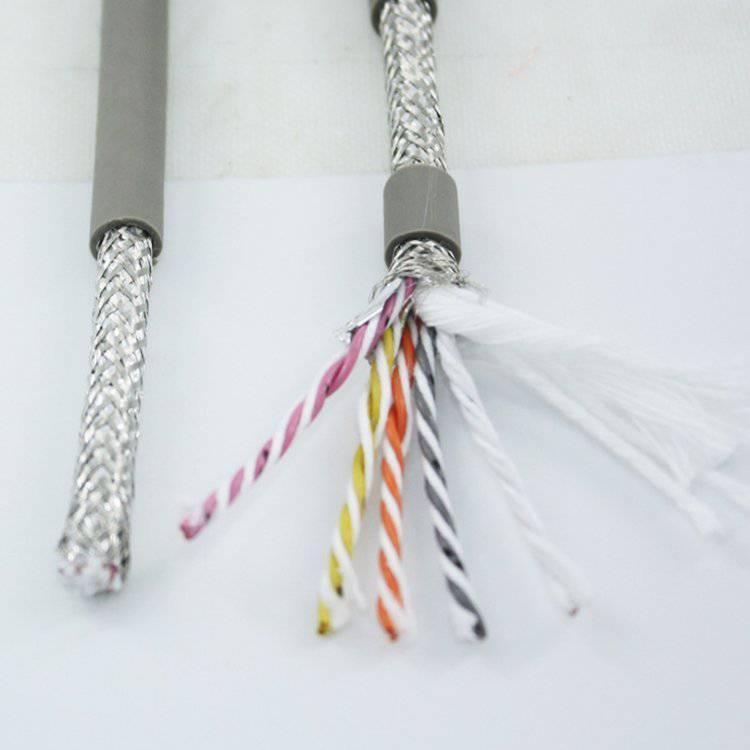
Braid coverage is the percentage of the cable surface area covered by the braid wires. At 85%, 15% of the surface is gaps — small rhomboid openings between the braid wires. These gaps are not defects; they are inherent to the braiding process and are acceptable for environments where the EMI field strength is moderate.
At 90% coverage, the gap area is reduced to 10% — a 33% reduction in uncovered area. The smaller gaps provide better shielding at higher frequencies because the gap dimension approaches the wavelength of the interfering signal. A 15% gap at 85% coverage might have a largest dimension of 1–2 mm — which is effective up to approximately 1 GHz (wavelength 300 mm). However, at the VFD switching frequency of 4–16 kHz, the relevant noise is not the fundamental but the harmonics — which extend to 30–100 MHz (wavelength 3–10 m). At these frequencies, gap size relative to wavelength matters — hence the improved performance of 90% coverage.
Transfer Impedance (Z_T) — The Quantifiable Measure
Braid coverage percentage is a visual geometric measurement — it tells you how much of the surface is covered, but not how well the shield actually performs electrically. Transfer impedance (Z_T) measures the shield's effectiveness directly:
- A voltage is applied between the shield and a return conductor at one end
- The voltage induced on a conductor inside the shield is measured at the other end
- Z_T = induced voltage / shield current × cable length (unit: Ω/m or mΩ/m)
- Lower Z_T = better shielding
When to Specify the Enhanced Shield
| Environment | Standard Shield (85%) | Enhanced Shield (90%) |
|---|---|---|
| Single servo axis, cable separated from power | Sufficient | Over-specified |
| Multi-axis machine, 3–6 servo cables in one drag chain | Marginal (cross-talk risk) | Recommended |
| Servo cable in same drag chain as motor power cables | Marginal | Recommended |
| CNC machine with 15+ kW VFD spindle drive nearby | Not recommended | Recommended |
| Welding cell — arc welding EMI (broadband to 100 MHz) | Not recommended | Required |
| Plasma cutting — high-frequency arc | Not recommended | Required |
The cost premium for 90% vs 85% braid coverage is approximately 10–15%. In a high-noise environment where a single encoder fault stops production, this premium is negligible compared to downtime cost.
Yichi Enhanced Shield Manufacturing
- Transfer impedance measured on new designs: Z_T per IEC 62153-4-3 (triaxial method) is measured on every new cable design as part of the qualification process. This provides a quantifiable shield performance metric — not just a visual coverage check
- Braid wire resistance controlled: Braid wire DC resistance is measured on production samples. Lower resistance = better low-frequency shielding. The braid wire alloy (tinned copper) and strand diameter are specified for ≤10 Ω/km overall braid resistance
- Braid coverage verified: Optical image analysis on production samples — ≥90% is the acceptance criterion. The visual measurement is a production quality check; the Z_T measurement is the design qualification test
- Shield continuity tested end-to-end: Every production length is tested for shield electrical continuity. An open circuit anywhere in the braid creates an unshielded cable section