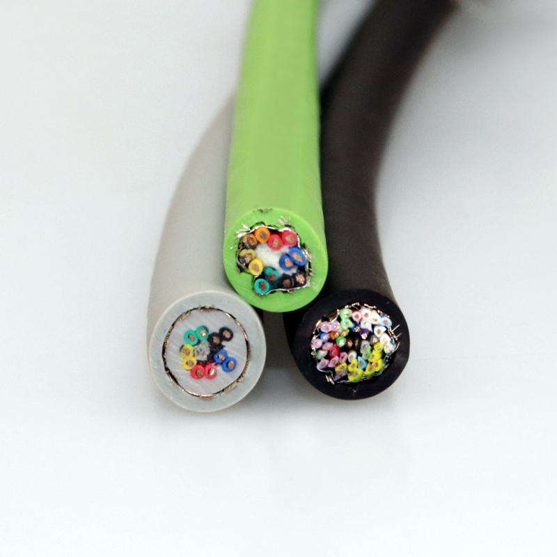
Composite Servo Cable (Power + Feedback) — All-in-One PUR Servo Cable Integrating Motor Power (0.6/1 kV) and Double-Shielded Encoder Feedback Pairs for Single-Cable Servo Drive-to-Motor Connection
Servo, Encoder & Signal Cables /Servo Feedback

Composite Servo Cable (Power + Feedback) — All-in-One PUR Servo Cable Integrating Motor Power (0.6/1 kV) and Double-Shielded Encoder Feedback Pairs for Single-Cable Servo Drive-to-Motor Connection

Composite servo cable (power + feedback): all-in-one PUR servo cable integrating motor power conductors (IEC 60228 Class 6, 1.5–35 mm², 0.6/1 kV) and individually shielded encoder feedback pairs (0.14–0.50 mm², PE/PP insulation) in a single cable. One cable from servo drive to servo motor — no separate power and feedback cables. Individual pair foil shields + overall tinned copper braid (≥85%). PUR jacket. Drag-chain-rated: 10+ million flex cycles. For single-cable servo drive systems (Siemens SIMODRIVE, Bosch Rexroth IndraDrive, and similar). CE, RoHS compliant.

Key Features

Power + feedback in one cable — 0.6/1 kV motor power (3-phase + PE, 1.5–35 mm²) plus encoder feedback pairs in a single PUR-jacketed assembly
One cable replaces two — eliminates the separate feedback cable; simpler cable management, fewer connectors, fewer failure points in the drag chain
Individual pair foil shielding + overall tinned copper braid (≥85%) — dual-layer EMI protection for encoder signals despite proximity to motor power conductors in the same cable
PE/PP low-capacitance insulation on feedback pairs — 40–60 pF/m; clean signal transmission over 10–50 m composite cable runs
Physical separation between power and feedback core groups — power cores in inner layer, feedback pairs in outer layer separated by filler elements; reduces capacitive coupling between power and signal
IEC 60228 Class 6 extra-fine stranded copper (all conductors) — drag-chain-rated; 10+ million flex cycles
PUR TMPU jacket — oil, coolant, and abrasion resistant; green (standard servo color) or black; –30°C cold-flex
CE, RoHS compliant; ISO 9001 manufactured

Applications

Single-cable servo drive systems — one cable connecting servo drive to servo motor; replaces separate power and feedback cablesCNC machine servo axes — composite cable for CNC mill, lathe, grinding machine servo axes where drag chain space is limitedRobotics and automation — composite servo cable for robot auxiliary axes, positioners, and automated machine servo drivesPackaging machinery — space-saving composite cable for multi-axis packaging machine servo drives with crowded drag chainsPrinting machinery — composite servo cable for printing press servo axes where registration accuracy demands clean encoder signalsMachine tool spindle motor — composite cable for spindle servo motor (power + encoder feedback or motor temperature sensor)

Technical Specifications

Conductor Material Bare copper, IEC 60228 Class 6 extra-fine stranded
Conductor Cross-Section — Motor Power 1.5 mm², 2.5 mm², 4 mm², 6 mm², 10 mm², 16 mm², 25 mm², 35 mm²
Power Cores 4 cores (3P+PE); +2 cores for motor brake (24 V DC) and +2 cores for motor temperature sensor (PTC/KTY)
Conductor Cross-Section — Feedback Pairs 0.14 mm², 0.22 mm², 0.34 mm², 0.50 mm²
Feedback Pairs 2, 3, 4, 5, 6, 8 individually shielded twisted pairs
Pair Shield Aluminium/polyester foil per pair; tinned copper drain wire
Overall Shield Tinned copper braid; ≥85% coverage
Core Insulation — Power TPE (thermoplastic elastomer); 90°C; oil-resistant
Core Insulation — Feedback PE or PP; low dielectric constant; high dielectric strength
Core Identification — Power Numbered + green/yellow PE per VDE 0293; U/V/W phase marking on request
Core Identification — Feedback Color-coded per DIN 47100 or drive-manufacturer-specific
Core Stranding Power cores in inner concentric layer → filler separator layer → feedback pairs in outer concentric layer
Inner Sheath TPE — separates core assembly from overall shield
Outer Jacket PUR TMPU; 2.0–3.5 mm; green (RAL 6018) or black
Rated Voltage — Power 0.6/1 kV (U₀/U)
Rated Voltage — Feedback 300 V
Test Voltage — Power 3 500 V AC, 5 minutes
Test Voltage — Feedback 1 500 V AC, 5 minutes
Capacitance (Feedback Core/Core) ≤60 pF/m at 800 Hz
Temperature — Flexing -30°C to +80°C
Temperature — Fixed -50°C to +90°C
Bend Radius (Drag Chain) 12× cable OD (larger than signal-only due to power core stiffness)
Flex Life >10 000 000 cycles (drag chain, 12× D/d)
Oil / Coolant Resistance IEC 60811-404
Flame Retardant IEC 60332-1-2
Certifications CE, RoHS; UL/CSA on request

Detailed Description

The Single-Cable Advantage

Traditional servo motor connection uses two separate cables:

  • Power cable: 4-core (3P+PE), 1.5–35 mm², 0.6/1 kV — connects the drive's power output to the motor's stator windings. Typically unshielded or with overall braid shield for EMC compliance
  • Feedback cable: Multi-pair shielded signal cable — connects the motor's encoder to the drive's feedback interface. Double-shielded, low capacitance
In a drag chain application (CNC machine, robot, packaging machine), these two cables occupy two drag chain compartments and require four connectors (drive power out, motor power in, drive feedback in, motor encoder out). Two cables also mean twice the cable management, twice the potential for connector failure, and twice the drag chain space.

The composite servo cable integrates both into one cable. One drag chain compartment, two connectors (one at each end — combined power+feedback connector), one cable to manage. The space saving in the drag chain is typically 25–35% compared to two separate cables of equivalent specification.

Power-to-Feedback Crosstalk — The Design Challenge

Putting 3-phase motor power (400–480 V, 10–40 A, 4–16 kHz PWM switching) and millivolt-level encoder signals (RS-422, ±2 V differential) in the same cable creates the worst-case scenario for capacitive crosstalk. The solution is three-fold:

1. Physical Layer Separation

The power cores are stranded in the innermost concentric layer. A separator layer — typically PU or aramid-reinforced filler rods — physically separates the power core layer from the feedback pair layer. This increases the distance between the noise source (power cores) and the victim (feedback pairs), reducing the parasitic capacitance between them. The separation layer thickness is typically 1.0–2.0 mm.

2. Individual Pair Shielding

Each feedback pair has its own aluminium/polyester foil shield with drain wire. This individual shielding provides the first stage of protection — capacitively coupled noise from the power cores is intercepted by the foil and shunted to ground via the drain wire, rather than coupling into the signal conductors.

3. Overall Braid Shield

The overall tinned copper braid provides the second stage — it intercepts any noise that penetrates past the individual pair shields and provides a low-impedance path to ground for the full cable length. The braid also serves as the cable's EMC shield for the motor power conductors — containing the PWM switching noise radiated from the power cores.

Cable Selection by Motor Power

The composite cable's power core cross-section must match the servo motor's rated current:

Motor Power (Typical)Continuous CurrentPower Core Cross-SectionFeedback PairsApprox. Cable OD
0.5–2 kW1.5–5 A4 × 1.5 mm²4 pairs (incremental encoder)12–14 mm
2–5 kW5–12 A4 × 2.5 mm²4 pairs (incremental encoder)14–16 mm
5–10 kW12–25 A4 × 4 mm²6 pairs (absolute encoder)17–19 mm
10–20 kW25–45 A4 × 6 mm²6 pairs (absolute encoder)19–22 mm
20–40 kW45–80 A4 × 10 mm²8 pairs (absolute + resolver)23–26 mm
40–70 kW80–130 A4 × 16 mm²8 pairs28–32 mm

Larger motors (≥70 kW) typically use separate power and feedback cables because the composite cable OD becomes impractical for standard drag chains and connectors.

Yichi Composite Servo Cable Manufacturing

  • Power-to-feedback capacitance verified: Capacitance between each power core and each feedback pair is measured on the first article of every new design — the design target is ≤10 pF/m per power-feedback pair. Excessive coupling indicates insufficient physical separation
  • Overall braid tested as EMC shield: The overall braid is tested for shielding effectiveness at the motor PWM frequency (4–16 kHz) and harmonics. The braid must provide ≥40 dB attenuation at 30 MHz for the cable to serve as the motor power cable's EMC shield
  • Combined connector termination: Composite cables require combined power+feedback connectors (typically Siemens Signal/Power hybrid, Bosch Rexroth hybrid, or custom — manufacturer-specific). We offer pre-terminated cables with molded connectors to customer specification
  • Drag chain test with power applied: Flex life test (10 000 000 cycles) is performed with the power cores energized at rated current — this simulates the thermal + mechanical stress of real operation, not just cold flexing

Product Inquiry

Product: Composite Servo Cable (Power + Feedback) — All-in-One PUR Servo Cable Integrating Motor Power (0.6/1 kV) and Double-Shielded Encoder Feedback Pairs for Single-Cable Servo Drive-to-Motor Connection

Add technical specifications (optional)

The more detail you provide, the faster and more accurate our quotation.

No file chosen

PDF, Office, image or CAD file — up to 5 MB

Need Help?

Certifications

ISO 9001
Quality
CE
European
RoHS
Environmental
TÜV
Certification

Need a Quote for This Product?

Send us your requirements and receive a detailed quotation within 24 hours.