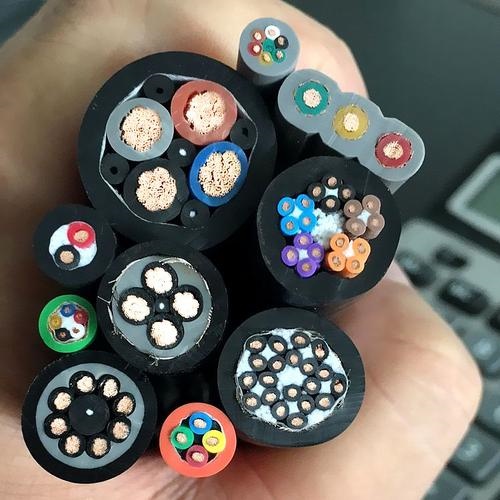
Detailed Description
Why "Composite" Matters — The Integration Argument
A 6-axis industrial robot contains between 6 and 12 servo motors (one per axis, plus optional auxiliary axes for external positioners or tool changers). Each motor requires power (3-phase + PE), brake power (2-core, 24 V DC), and encoder feedback (4–8 shielded signal pairs). Additionally, the end effector — a welding gun, gripper, vision camera, or tool changer — requires its own power, signal, and data connections. A robot wiring diagram quickly becomes a dense thicket of individual cables.
The traditional approach — individual cables for each function, bundled together and routed through the robot arm — has three problems:
- Space: The cable path through a 6-axis robot arm is narrow — typically 30–50 mm diameter at the wrist. Routing 6–12 individual cables through this space is physically impossible for all but the largest robots
- Friction: Individual cables rub against each other as the arm moves. The outer jacket of each cable wears against its neighbors. After millions of cycles, friction-induced jacket failure is a leading cause of robot cable failure
- Torsion imbalance: A bundle of individual cables does not twist as a single unit. Each cable twists at a slightly different rate, creating internal friction and stress concentrations where cables bind against each other
Data Bus Integration — Why Build It Into the Cable?
Ethernet and fieldbus cables (PROFINET, EtherCAT, CAN bus) are manufactured to precise impedance and attenuation specifications. Integrating these data elements into a composite cable — rather than running separate data cables alongside a power+signal composite — requires:
- Controlled impedance maintained through the stranding process: A CAT5e twisted pair has a characteristic impedance of 100 ±15 Ω at 100 MHz. This impedance depends on the conductor diameter, insulation thickness, and dielectric constant — and critically, on the pair's position relative to other conductors in the cable. If the pair is crushed between two large power conductors during stranding, the impedance shifts. Our stranding process uses spacer elements and defined conductor positions to maintain data pair geometry throughout the cable cross-section
- Crosstalk isolation: A 10 mm² power conductor carrying 20 A at 50 Hz with VFD harmonics generates significant electromagnetic fields. The data pairs are physically separated from the power conductors by PU filler rods and signal pair layers — the power cores are in the center, signal pairs in the middle layer, and data pairs in the outermost core layer, maximally distant from the power conductors
- Impedance tested post-cabling: Network analyzer measurement of characteristic impedance and return loss on data pairs after complete cable assembly — not just on the bare pairs before cabling. This ensures the stranding and jacketing process has not degraded the data transmission performance
Yichi Composite Cable Manufacturing
- Custom configuration engineering: Every composite cable is customer-specific. Our application engineers work from the robot wiring diagram to design the cable cross-section — conductor count, cross-section, pair count, data element type, shielding, and overall dimensions. A cross-section drawing is provided for customer approval before manufacture
- Data pair impedance verified: Network analyzer (Vector Network Analyzer, VNA) measurement of characteristic impedance (TDR method), return loss, and insertion loss on data pairs after final cabling. Acceptance: impedance within ±10 Ω of nominal; return loss ≥20 dB at operating frequency
- SRL (structural return loss) monitored: Irregularities in the cable structure (varying lay length, inconsistent conductor diameter, insulation eccentricity) cause reflections that degrade data transmission. SRL is measured and compared to specification limits
- Torsion life tested with all elements active: Torsion test at ±180°/m with power conductors energized at rated current, signal pairs carrying 10 MHz test signal, and data pairs transmitting Ethernet frames — all monitored for interruption during the 10 000 000 cycle test. This is the definitive qualification test