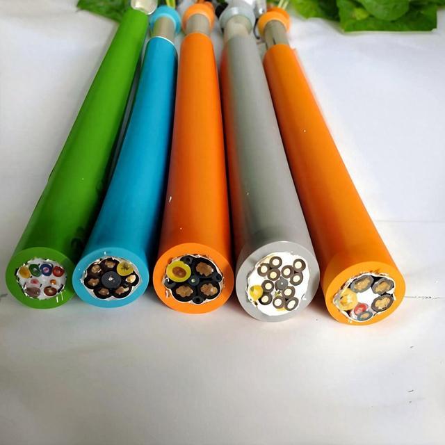
Robot Arm Torsion Cable — SZ-Stranded Torsion-Optimized PUR Cable Rated ±270°/m for 6-Axis Industrial Robot Wrist (Axis 4/5/6) and High-Torsion Articulated Arm Segments
Robot & Automation Cables /Composite Robot Cables

Robot Arm Torsion Cable — SZ-Stranded Torsion-Optimized PUR Cable Rated ±270°/m for 6-Axis Industrial Robot Wrist (Axis 4/5/6) and High-Torsion Articulated Arm Segments

Robot arm torsion cable: SZ-stranded torsion-optimized PUR cable purpose-built for the high-torsion wrist and articulated arm segments of 6-axis industrial robots. IEC 60228 Class 6 extra-fine stranded copper with alternating SZ-lay stranding and anti-torsion PU filler rods. Rated ±180°/m (standard) to ±270°/m (enhanced). TPE/PP insulation. PUR jacket. Available in power-only, control-only, and combined power+control configurations. 10+ million torsion cycles. For robot axes 4, 5, and 6 — wrist roll, wrist pitch, and wrist rotate — where the cable experiences continuous torsional stress. CE, RoHS compliant.

Key Features

Purpose-built for torsion — SZ (alternating S-lay/Z-lay) stranding with anti-torsion PU filler rods; cable twists freely around its longitudinal axis without conductor damage
Torsion-rated ±180°/m standard; ±270°/m enhanced — covers the full torsion range of axes 4 (wrist roll) and 6 (wrist rotate) on 6-axis industrial robots
IEC 60228 Class 6 extra-fine stranded bare copper — the finest stranding for maximum fatigue resistance under combined bending + torsion
TPE or PP core insulation — low-friction surface allows conductors to move relative to each other during torsion; prevents internal abrasion
Anti-torsion filler rods: solid PU or aramid-reinforced profiles — fill interstices and provide elastic recovery force that returns the cable to neutral after twist release
PUR TMPU outer jacket — oil, coolant, and weld-spatter resistant; maintains flexibility at the high flex/torsion rates of robot wrist motion
Available configurations: power only (0.6/1 kV), control only (300/500 V), or combined power+control — select based on the robot axis function
CE, RoHS compliant; ISO 9001 manufactured

Applications

Robot axis 4 (wrist roll) — torsion cable segment through the robot forearm into the wrist roll axis; continuous ±180° rotationRobot axis 6 (wrist rotate) — final torsion cable segment from wrist to end effector mounting flange; ±270° rotation with tool changerRobot axis 5 (wrist pitch) — combined bending + torsion cable segment at the wrist pitch axis; bending in one plane + torsional twistArticulated robot arm — torsion cable segments through the elbow (axis 3) for robots with offset wrist design where the cable path includes a torsional componentRobot external axis positioner — torsion cable for rotary table, tilt positioner, or track motion unit servo motor connectionsSCARA robot Z-axis — torsional cable segment for SCARA robot vertical (Z) axis where the quill rotates continuously

Technical Specifications

Conductor Material Bare copper, IEC 60228 Class 6 extra-fine stranded
Conductor Cross-Section — Power (Optional) 1.5 mm², 2.5 mm², 4 mm², 6 mm², 10 mm², 16 mm²
Conductor Cross-Section — Control (Optional) 0.22 mm², 0.34 mm², 0.50 mm², 0.75 mm², 1.0 mm², 1.5 mm²
Core Count 2–24 cores (power or control or combined)
Core Insulation — Power TPE; 90°C; low-friction for torsion movement
Core Insulation — Control PP (polypropylene); low capacitance; low friction
Core Identification Numbered per VDE 0293; color coding on request
Stranding Pattern SZ (alternating S-lay/Z-lay sections, 0.5–1.0 m each); lay length optimized for rated torsion angle
Anti-Torsion Fillers Solid PU rods or aramid-reinforced PU profiles; elastic recovery after twist release
Central Element (Optional) Aramid yarn (Kevlar) tensile strength member; or PU center rod for torsion recovery
Inner Sheath TPE; low-friction sliding layer between core assembly and jacket
Outer Jacket PUR TMPU; 1.5–3.0 mm; halogen-free; black or orange
Rated Voltage — Power 0.6/1 kV (U₀/U)
Rated Voltage — Control 300/500 V (U₀/U)
Test Voltage 3 500 V (power); 2 000 V (control)
Temperature — Flexing/Torsion -30°C to +80°C
Temperature — Fixed -50°C to +90°C
Torsion Rating — Standard ±180° per meter
Torsion Rating — Enhanced ±270° per meter (on request)
Torsion Life (Standard) >10 000 000 cycles at ±180°/m
Torsion Life (Enhanced) >5 000 000 cycles at ±270°/m
Bend Radius (Flexing) 7.5× cable OD
Bend Radius (Torsion) 10× cable OD
Torsion Test Length 1.0 m between clamps (standard per VDE 0472 / EN 50396 torsion test)
Oil / Coolant Resistance IEC 60811-404
Flame Retardant IEC 60332-1-2
Certifications CE, RoHS

Detailed Description

The Physics of Torsion — Why Standard Cables Fail

A standard flexible cable — even a drag-chain-rated high-flex cable — is designed for bending in one plane. When a bending force is applied, the conductors on the outside of the bend stretch (tension) and those on the inside compress. The cable's stranding pattern (typically S-lay or Z-lay, single direction) accommodates this by allowing the conductors to slide relative to each other within the core assembly.

Torsion is fundamentally different. When a cable is twisted around its longitudinal axis:

  • Conductors on the outside of the cable follow a helical path — longer than the straight centerline
  • Conductors near the center follow a shorter path — closer to the axis of rotation
  • The difference in path length means the outer conductors stretch (tension) and the inner conductors compress — simultaneously, around the entire circumference
After thousands of torsion cycles, the outer conductors permanently elongate (neck down, increasing resistance) while the inner conductors buckle (corkscrew, creating inter-conductor shorts). Standard single-direction lay stranding accelerates this because all conductors respond to torsion in the same direction — the stress is additive rather than canceling.

SZ Stranding — The Torsion Solution

SZ stranding alternates the direction of the helical lay along the cable length, switching between S-lay and Z-lay in repeating sections of 0.5–1.0 meter:

SectionLay DirectionConductor Response
Section 1S-lay (left-hand helix)Compresses under clockwise twist
Section 2Z-lay (right-hand helix)Stretches under clockwise twist
Section 3S-layCompresses

When the cable is twisted clockwise, the S-lay sections tighten (conductors compress) while the Z-lay sections loosen (conductors stretch). The net stress on any given conductor is approximately zero — the compression in the S section cancels the tension in the Z section, integrated over the conductor length.

The anti-torsion filler rods serve two functions:

  • They fill the interstices between conductors, preventing conductors from migrating into voids during torsion
  • They provide elastic recovery force — when the twist is released, the filler rods' stored elastic energy returns the cable to its neutral, untwisted position

Torsion Angle vs Robot Axis — What Rating Do You Need?

Robot AxisMotionTypical Torsion AngleRecommended Cable Rating
Axis 1 (base rotate)Rotation, bending only0° (no torsion at the cable)High-flex bending, not torsion
Axis 2 (shoulder)Bending only0°High-flex bending
Axis 3 (elbow)Bending, minor torsion±30°High-flex bending + torsion
Axis 4 (wrist roll)Continuous rotation±180°±180°/m torsion-rated
Axis 5 (wrist pitch)Bending + moderate torsion±90°±180°/m torsion-rated
Axis 6 (wrist rotate)Continuous rotation with tool changer±270° (with tool changer)±270°/m torsion-rated

The cable segments for axes 4, 5, and 6 are where torsion-rated cable is mandatory — standard flexible cable will fail within weeks at these locations.

Yichi Torsion Cable Manufacturing

  • SZ lay length matched to torsion rating: The S/Z section length (0.5–1.0 m) is matched to the expected torsion angle and cable diameter. The ratio of section length to cable lay length is a critical design parameter — verified on every production run
  • Anti-torsion filler material engineered: The filler rods are not generic PU — they are formulated with specific Shore hardness (typically 70–85 A) and elastic modulus to provide the correct recovery force for the cable diameter and expected torsion angle
  • Sliding layer between core and jacket: A thin TPE inner sheath acts as a slip plane between the core assembly and the PUR outer jacket. Without this layer, the jacket bonds to the outermost conductors and restricts their torsional movement — concentrating stress rather than distributing it
  • Torsion test with axial load: The torsion test is performed with the cable under a defined axial load (typically 50–100 N for robot cables) to simulate the installed condition where the cable is under slight tension from its own weight and connector retention force

Product Inquiry

Product: Robot Arm Torsion Cable — SZ-Stranded Torsion-Optimized PUR Cable Rated ±270°/m for 6-Axis Industrial Robot Wrist (Axis 4/5/6) and High-Torsion Articulated Arm Segments

Add technical specifications (optional)

The more detail you provide, the faster and more accurate our quotation.

No file chosen

PDF, Office, image or CAD file — up to 5 MB

Need Help?

Certifications

ISO 9001
Quality
CE
European
RoHS
Environmental
TÜV
Certification

Need a Quote for This Product?

Send us your requirements and receive a detailed quotation within 24 hours.