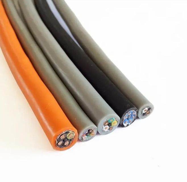
Encoder Servo Feedback Cable — Pure Feedback Signal Cable with Individual Pair Shielding and Low-Capacitance PE Insulation for Incremental and Absolute Servo Motor Encoder-to-Drive Signal Transmission
Servo, Encoder & Signal Cables /Servo Feedback

Encoder Servo Feedback Cable — Pure Feedback Signal Cable with Individual Pair Shielding and Low-Capacitance PE Insulation for Incremental and Absolute Servo Motor Encoder-to-Drive Signal Transmission

Encoder servo feedback cable: pure feedback signal cable for servo motor encoder-to-drive signal transmission. IEC 60228 Class 6 extra-fine stranded copper signal pairs (0.14–0.50 mm², 2–12 pairs) with PE/PP low-capacitance insulation (40–60 pF/m). Individually shielded pairs (aluminium/polyester foil + drain wire) plus overall tinned copper braid shield (≥85%). PUR jacket. 300 V rated. For incremental (A/B/Z), absolute (EnDat, Hiperface, BiSS, SSI), and resolver (SIN/COS) encoder feedback — where the motor power is supplied through a separate cable. Drag-chain-rated: 10+ million flex cycles. CE, RoHS compliant.

Key Features

Pure feedback signal construction — no power conductors; optimized for lowest possible capacitance and highest signal integrity for encoder data transmission
Individually shielded pairs (aluminium/polyester foil + drain wire) + overall tinned copper braid (≥85%) — dual-layer EMI protection optimized for signal frequencies up to 16 MHz
PE (polyethylene) or PP (polypropylene) core insulation — low dielectric constant (2.3–2.4), capacitance 40–60 pF/m; clean signal edges at multi-MHz encoder data rates
IEC 60228 Class 6 extra-fine stranded copper — maximum flexibility for drag chain; smaller OD than composite cable (no power cores)
PUR TMPU jacket — oil, coolant, and abrasion resistant; green (standard) or black; –30°C cold-flex
Up to 12 individually shielded pairs — supports multi-encoder systems, dual-feedback motors, and motors with additional temperature and vibration sensors
Capacitance-matched pair design — consistent lay length and insulation thickness ensure all pairs have matched capacitance for predictable signal timing
CE, RoHS compliant; ISO 9001 manufactured

Applications

Incremental encoder feedback — separate feedback cable for servo motor incremental encoder (A, A-not, B, B-not, Z, Z-not) when motor power is on a separate cableAbsolute encoder feedback — EnDat, Hiperface, BiSS, SSI digital absolute encoder cable for position-critical servo applicationsResolver feedback — dedicated resolver cable (excitation + SIN/COS) for servo motor resolver position feedbackDual-feedback servo motor — multi-pair cable for motors with both incremental and absolute encoders, or encoder + resolverLinear encoder feedback — dedicated signal cable for linear scale encoders on CNC machine axes and precision measurement systemsMotor temperature and vibration monitoring — additional shielded pairs for motor PTC thermistor, KTY temperature sensor, and vibration sensor signals alongside encoder data

Technical Specifications

Conductor Material Bare copper, IEC 60228 Class 6 extra-fine stranded
Conductor Cross-Section 0.14 mm², 0.22 mm², 0.34 mm², 0.50 mm²
Signal Pairs 2, 3, 4, 5, 6, 8, 10, 12 individually shielded twisted pairs
Pair Shield Aluminium/polyester foil per pair; 100% coverage; tinned copper drain wire, 0.14 mm²
Overall Shield Tinned copper braid; ≥85% coverage; braid angle 30–45°
Overall Drain Wire Tinned copper, 0.22 mm²; in continuous contact with braid
Core Insulation PE or PP; low dielectric constant; 0.2–0.4 mm wall thickness
Insulation Color Code Per DIN 47100 or drive-manufacturer-specific
Core Stranding Pairs cabled in concentric layers with non-hygroscopic filler elements
Inner Sheath PVC or TPE
Outer Jacket PUR TMPU; 1.2–2.0 mm; green (RAL 6018) or black
Rated Voltage (U₀/U) 300 V
Test Voltage (Core/Core) 1 500 V AC, 5 minutes
Test Voltage (Core/Shield) 1 500 V AC, 5 minutes
Insulation Resistance ≥5 GΩ·km at 20°C
Capacitance (Core/Core) ≤60 pF/m at 800 Hz
Capacitance (Core/Shield) ≤100 pF/m at 800 Hz
Characteristic Impedance 100–150 Ω per pair at 1 MHz
Temperature — Flexing -30°C to +80°C
Temperature — Fixed -50°C to +90°C
Bend Radius (Flexing) 7.5× cable OD
Bend Radius (Drag Chain) 10× cable OD
Flex Life >10 000 000 cycles (drag chain, 10× D/d)
Travel Speed (Drag Chain) Up to 300 m/min
Oil / Coolant Resistance IEC 60811-404
Flame Retardant IEC 60332-1-2
Certifications CE, RoHS; UL AWM 20233 on request

Detailed Description

Pure Feedback vs Composite — When One Cable Is Better Than All-in-One

The composite servo cable (power + feedback in one cable) is the convenient single-cable solution. But there are applications where a separate pure feedback cable — encoder signals only, no power conductors — is the correct specification:

1. Retrofit and Existing Installations

Many servo motors in the field have separate power and feedback connectors. Replacing the motor with a single-cable motor is an expensive retrofit. A pure feedback cable replaces the existing feedback cable without changing the power cable, connectors, or motor.

2. Cable Routing Constraints

In some machine designs, the power cable and feedback cable follow different paths. The power cable may route through a cable tray on one side of the machine, while the feedback cable routes through the drag chain on the other side — to maximize separation and minimize EMI. A composite cable forces both power and feedback into the same path, which may not be the optimal routing.

3. Feedback-Only Applications

Linear encoders, rotary encoders on non-motor shafts, and external position measurement systems require a feedback signal cable but no motor power. Specifying a composite cable for these applications wastes the power cores — adding cost, weight, and cable OD for conductors that will not be terminated.

4. Flexible Configuration

Separate power and feedback cables allow independent replacement. If the feedback cable is damaged (the more fragile of the two), only the feedback cable needs replacement — not the entire composite cable. In a production environment where downtime costs $500–5 000 per hour, the ability to replace only the failed cable can be significant.

Pair Allocation by Encoder Type

The number of pairs required depends on the encoder type:

Encoder TypePairs RequiredSignal Allocation
Incremental (RS-422)3–4 pairsA/A\, B/B\, Z/Z\, +1 pair for motor temp
Incremental + commutation5–6 pairs+U/U\, V/V\, W/W\ (or Hall sensors)
Absolute — EnDat 2.1/2.22–3 pairsData+/Data–, Clock+/Clock–, +1 pair for power
Absolute — Hiperface3–4 pairsData+/Data–, + SIN/COS, +1 pair for power
Absolute — BiSS C2–3 pairsData+/Data–, Clock+/Clock–, +1 pair for power
Absolute — SSI2–3 pairsData+/Data–, Clock+/Clock–, +1 pair for power
Resolver3 pairsExcitation+, SIN/SIN\, COS/COS\
Dual encoder (motor + load side)6–8 pairsTwo encoder sets + temp sensors
Full-featured: encoder + resolver + temp + vibration8–12 pairsAll feedback signals in one cable

For motors with a single incremental encoder and PTC temperature sensor, 4 pairs is the standard configuration. For high-end absolute encoder motors with dual feedback and condition monitoring sensors, 10–12 pairs may be required.

Yichi Pure Feedback Cable Manufacturing

  • Pair capacitance matched to ±5%: All pairs in a cable are capacitance-tested. The difference between the highest-capacitance pair and lowest-capacitance pair must be ≤5% of the average. Matched capacitance means matched signal propagation delay — critical for multi-channel encoder interfaces where timing skew between channels causes position error
  • No power core contamination: Pure feedback cables are manufactured on dedicated production lines that do not process power conductors. This eliminates the risk of a stray power core strand migrating into a signal pair during stranding — a defect that would create an inter-conductor short that is invisible to routine production testing
  • Small OD advantage: Without power cores, the pure feedback cable OD is 20–40% smaller than the equivalent composite cable for the same encoder type — smaller OD means tighter bend radius capability and less drag chain space required
  • Labeled with encoder type compatibility: Cable jacket is printed with the encoder interface type(s) the cable is designed for (e.g., "ENCODER CABLE — EnDat 2.2 / BiSS C — 4×2×0.22 mm² + 2×0.50 mm² — PUR") — immediately identifiable during installation and maintenance

Product Inquiry

Product: Encoder Servo Feedback Cable — Pure Feedback Signal Cable with Individual Pair Shielding and Low-Capacitance PE Insulation for Incremental and Absolute Servo Motor Encoder-to-Drive Signal Transmission

Add technical specifications (optional)

The more detail you provide, the faster and more accurate our quotation.

No file chosen

PDF, Office, image or CAD file — up to 5 MB

Need Help?

Certifications

ISO 9001
Quality
CE
European
RoHS
Environmental
TÜV
Certification

Need a Quote for This Product?

Send us your requirements and receive a detailed quotation within 24 hours.