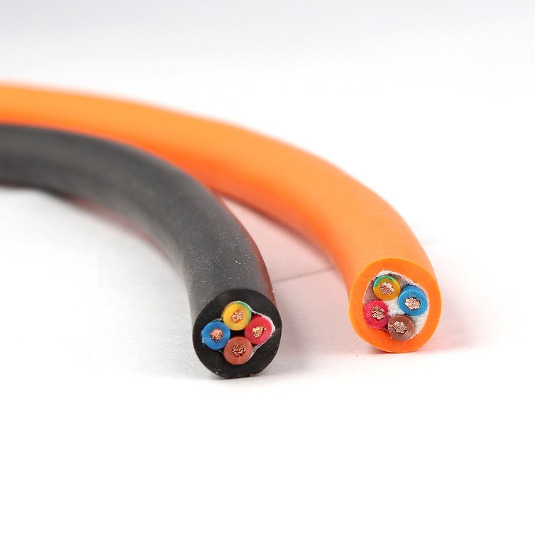
Servo Motor Cable — Double-Shielded High-Flex PUR Feedback Cable with Low-Capacitance PE/PP Insulation for Servo Motor Encoder, Resolver, and Absolute Position Feedback Systems
Servo, Encoder & Signal Cables /Servo Feedback

Servo Motor Cable — Double-Shielded High-Flex PUR Feedback Cable with Low-Capacitance PE/PP Insulation for Servo Motor Encoder, Resolver, and Absolute Position Feedback Systems

Servo motor cable: double-shielded high-flex PUR feedback cable for servo motor encoder, resolver, and absolute position feedback systems. IEC 60228 Class 6 extra-fine stranded copper signal pairs (0.14–0.50 mm², 2–8 pairs) with PE or PP low-capacitance insulation (40–60 pF/m). Individual pair shielding (aluminium/polyester foil + drain wire) plus overall tinned copper braid shield (≥85% coverage). PUR TMPU jacket. 300 V rated. Designed for drag chain and continuous flexing in CNC machines, packaging machinery, textile machinery, and automated production lines. 10+ million flex cycles. Compatible with Siemens, Bosch Rexroth, Yaskawa, Mitsubishi, Fanuc, Lenze, and B&R servo systems. CE, RoHS compliant.

Key Features

Double-shielded construction: individual aluminium/polyester foil shield per pair (100% coverage) + overall tinned copper braid (≥85% coverage) — broadband EMI protection for clean encoder and resolver signals
PE (polyethylene) or PP (polypropylene) core insulation — low dielectric constant (2.3–2.4), low capacitance (40–60 pF/m core-to-core) for minimal signal attenuation over 10–50 m cable runs
IEC 60228 Class 6 extra-fine stranded bare copper — maximum flexibility for drag chain and continuous flexing applications; 10+ million flex cycles
Individually shielded twisted pairs — each encoder channel (A, B, Z, U, V, W, data+, data-) in its own shielded pair, eliminating cross-talk between channels
PUR TMPU jacket — oil-resistant (IEC 60811), coolant-resistant, abrasion-resistant; –30°C cold-flex; standard green (RAL 6018) per servo cable industry convention
Capacitance-controlled pair geometry — consistent lay length and insulation wall thickness ensure stable impedance for digital encoder interfaces (EnDat, Hiperface, BiSS, SSI)
Drain wire per pair + overall drain wire — each shield independently terminable; low-impedance ground path for high-frequency noise currents
CE, RoHS compliant; ISO 9001 manufactured; compatible with major servo drive brands

Applications

Servo motor encoder feedback — incremental encoder signals (A, A-not, B, B-not, Z, Z-not) from motor to servo drive in CNC, robotics, and automationAbsolute encoder feedback — EnDat, Hiperface, BiSS, and SSI digital absolute encoder communication from motor to driveResolver feedback — resolver excitation and SIN/COS signal pairs from servo motor resolver to driveLinear motor encoder — feedback cable for linear motor position encoders (optical or magnetic) in high-speed linear motion systemsCNC machine servo axes — drag-chain-rated feedback cable for CNC mill, lathe, and machining center servo axesPackaging and textile machinery — high-flex servo feedback cable for high-cycle packaging, printing, and textile machines

Technical Specifications

Conductor Material Bare copper, IEC 60228 Class 6 extra-fine stranded
Conductor Cross-Section 0.14 mm², 0.22 mm², 0.34 mm², 0.50 mm² (signal pairs); 0.75–2.5 mm² (power pairs for motor brake/temperature sensor)
Signal Pairs 2, 3, 4, 5, 6, 8 individually shielded twisted pairs
Pair Shield Aluminium/polyester foil per pair; tinned copper drain wire, 0.14 mm²
Overall Shield Tinned copper braid; ≥85% coverage; braid angle 30–45°
Core Insulation PE (polyethylene) or PP (polypropylene); low dielectric constant; high dielectric strength
Insulation Color Code Per DIN 47100 or drive-manufacturer-specific (green/yellow/blue/red/black/white/grey/brown/etc.)
Pair Identification Color-coded per pair; numbering on request
Core Stranding Twisted pairs cabled in concentric layers with non-hygroscopic filler elements
Inner Sheath PVC or TPE — separates core assembly from overall shield
Outer Jacket PUR TMPU; 1.2–2.0 mm; green (RAL 6018, standard servo color) or black
Rated Voltage 300 V (U₀/U per VDE 0812 for signal cables)
Test Voltage (Core/Core) 1 500 V AC, 5 minutes
Test Voltage (Core/Shield) 1 500 V AC, 5 minutes
Insulation Resistance ≥5 GΩ·km at 20°C
Capacitance (Core/Core at 800 Hz) ≤60 pF/m
Capacitance (Core/Shield at 800 Hz) ≤100 pF/m
Characteristic Impedance (at 1 MHz) 100–150 Ω per pair (design-dependent)
Temperature — Flexing -30°C to +80°C
Temperature — Fixed -50°C to +90°C
Minimum Bend Radius (Flexing) 7.5× cable outer diameter
Minimum Bend Radius (Drag Chain) 10× cable outer diameter
Flex Life >10 000 000 cycles (drag chain, 10× D/d)
Travel Speed (Drag Chain) Up to 300 m/min
Acceleration (Drag Chain) Up to 50 m/s²
Oil / Coolant Resistance IEC 60811-404
Flame Retardant IEC 60332-1-2
Certifications CE, RoHS; UL AWM 20233 on request

Detailed Description

The Servo Feedback Signal Chain — Why Cable Quality Matters

A servo motor's encoder generates position and speed data that the servo drive uses to control the motor — typically at update rates of 2–16 kHz for standard drives and up to 62.5 µs (16 kHz) for high-performance systems. The feedback cable carries these signals from the motor-mounted encoder to the drive's feedback interface.

The signals are electrically fragile:

  • Incremental encoder A/B: 5 V differential (RS-422), up to 500 kHz pulse frequency. At 500 kHz, a single pulse is 2 µs wide. Cable capacitance rounds the pulse edges — if the rise time exceeds 0.5 µs, the drive's decoder may misread the pulse count, causing position error
  • Absolute encoder digital (EnDat, BiSS, SSI): Clock frequencies from 100 kHz to 16 MHz. At 16 MHz, the clock period is 62.5 ns. Cable capacitance and inductance must be controlled to maintain signal integrity — the cable is effectively a transmission line
  • Resolver SIN/COS: Analog signals at 4–10 kHz excitation frequency, mV-level amplitude. Noise from adjacent motor power cables directly corrupts the angular position calculation — every 1 mV of noise translates to a measurable angular error
A poorly specified feedback cable — with high capacitance, inadequate shielding, or non-controlled impedance — degrades these signals, causing the drive to report encoder faults, lose position, or trip on "feedback loss" errors. In a CNC machine cutting a $10 000 workpiece, a feedback fault mid-cycle scrapes the part. The cost of the cable is trivial compared to the cost of the failure.

Capacitance — The Critical Parameter

For digital encoder signals at multi-MHz frequencies, cable capacitance is the dominant signal degradation mechanism. Capacitance per meter (pF/m) is determined by:

  • Insulation material: PE and PP have dielectric constants of 2.3–2.4. PVC has a dielectric constant of 4–6. The cable's capacitance is directly proportional to the dielectric constant — PE/PP cable has approximately half the capacitance of PVC cable of the same geometry. This is why servo feedback cables use PE/PP insulation: every picofarad of capacitance per meter rounds the digital pulse edges and limits the maximum cable length
  • Insulation thickness: Thinner insulation = higher capacitance (conductors closer together). But thinner insulation = lower voltage rating and less mechanical robustness. The servo cable insulation wall thickness is a balance — typically 0.2–0.4 mm for 0.14–0.34 mm² signal conductors
  • Pair twist lay length: Tighter twist (shorter lay length) = better common-mode noise rejection but slightly higher capacitance per meter. Servo cables optimize for the mid-range — lay length of 30–50 mm per twist

Cable Length Limits for Digital Encoder Interfaces

The maximum cable length for a digital encoder interface depends on the clock/data frequency and the cable's capacitance per meter:

Encoder InterfaceClock / Data RateMax Cable LengthLimiting Factor
Incremental (RS-422)500 kHz pulse50 mCapacitance (pulse edge rounding)
EnDat 2.12 MHz clock50 mCapacitance + timing
EnDat 2.216 MHz clock10 mTransmission line effects
Hiperface DSLDigital, 100 Mbps10 mSignal attenuation
BiSS C10 MHz clock25 mCapacitance + crosstalk
SSI1 MHz clock50 mCapacitance
Resolver (analog)4–10 kHz excitation100 mCable resistance (voltage drop)

For cable lengths exceeding these limits, an active line driver/repeater at the motor end is required — or the drive must support the longer length with reduced clock frequency.

Yichi Servo Cable Manufacturing

  • Capacitance measured on every production length: Core-to-core and core-to-shield capacitance at 800 Hz is measured as a routine production test. Values exceeding the specification trigger rejection — capacitance is the single most critical electrical parameter for a servo feedback cable
  • Pair twist lay length verified: Optical measurement of pair lay length on production samples. Inconsistent lay length causes pair-to-pair capacitance variation and unpredictable signal timing skew
  • Shield coverage optically measured: Overall braid coverage ≥85% verified by image analysis. Braid angle 30–45° from cable axis — balanced for coverage vs flexibility
  • Drain wire continuity tested: Each individually shielded pair's drain wire is continuity-tested. An open drain wire means the pair's foil shield is electrically floating — providing zero capacitive noise protection
  • Green jacket (RAL 6018): Standard servo cable color per industry convention — visually identifies the cable as a servo feedback cable in the control cabinet and on the machine

Product Inquiry

Product: Servo Motor Cable — Double-Shielded High-Flex PUR Feedback Cable with Low-Capacitance PE/PP Insulation for Servo Motor Encoder, Resolver, and Absolute Position Feedback Systems

Add technical specifications (optional)

The more detail you provide, the faster and more accurate our quotation.

No file chosen

PDF, Office, image or CAD file — up to 5 MB

Need Help?

Certifications

ISO 9001
Quality
CE
European
RoHS
Environmental
TÜV
Certification

Need a Quote for This Product?

Send us your requirements and receive a detailed quotation within 24 hours.