Detailed Description
What Is a Twisted Pair Shielded Cable?
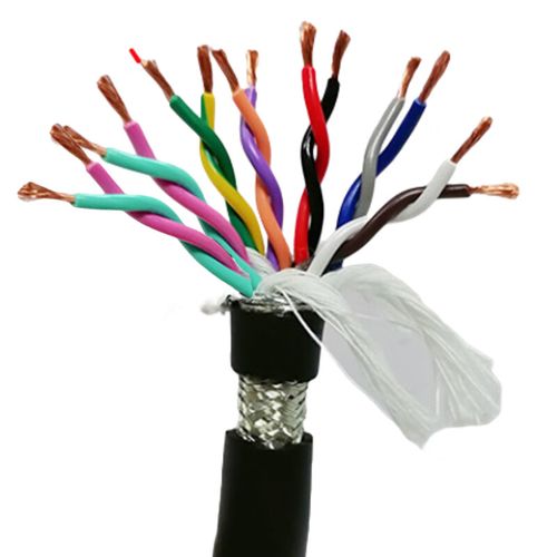
A twisted pair shielded cable combines two complementary noise-rejection techniques in a single cable design: twisted pair geometry and an overall conductive shield. Each signal circuit uses two conductors twisted together — any external electromagnetic field induces near-identical voltages on both conductors (common-mode), which the differential receiver at the load rejects. The overall shield — typically a tinned copper wire braid — intercepts radiated EMI before it reaches the conductors, draining induced currents to ground.
This cable type is the standard solution for industrial signal transmission where:
- Signals are differential (RS-485, RS-422, CAN bus, encoder feedback)
- The cable runs alongside power wiring in cable trays, conduits, or machinery
- The environment contains variable-frequency drives, contactors, or arc-welding equipment producing broadband EMI
For wiring that stays inside a single control cabinet, machine enclosure, or instrument chassis and is measured in centimetres rather than tens of metres, an individually foil-shielded twisted pair wire is the correct construction instead. A braid-shielded multi-pair cable is specified for runs between enclosures; it is not the economical choice for panel-internal point-to-point wiring.
Shielded vs Unshielded Twisted Pair — Noise Rejection Comparison
| Parameter | Unshielded Twisted Pair (UTP) | Shielded Twisted Pair (STP / Braid) |
|---|---|---|
| EMI rejection mechanism | Common-mode rejection via twist only (C-MRR) | C-MRR + Faraday cage shield absorption |
| Typical noise attenuation at 1 MHz | 10–15 dB (depends on twist uniformity) | 25–35 dB (braid ≥85% coverage) |
| Electrostatic (E-field) coupling | Some — relies entirely on balanced impedance | Blocked — braid intercepts E-field before it reaches conductors |
| Susceptibility to nearby VFD cable | Moderate to high — VFD switching noise couples inductively | Low — braid provides low-impedance path for induced shield currents |
| Crosstalk between adjacent cables | Yes — unshielded cables laid in the same tray couple | Greatly reduced — braid prevents external capacitive coupling |
| Cost | Lower | Higher (copper for braid, additional manufacturing step) |
| Best application | Office LAN (Ethernet), telephone, short low-noise runs | Industrial signal, fieldbus, encoder, analog sensor near power equipment |
The additional cost of the braid shield is typically recovered many times over in avoided commissioning delays, intermittent faults, and downtime caused by noise-induced communication errors.
Common Signal Protocols Served
| Protocol | Electrical Standard | Impedance Requirement | Twisted Pair Suitability |
|---|---|---|---|
| RS-485 / MODBUS RTU | TIA/EIA-485-A, differential | 100–120 Ω | ✅ Ideal — twisted pair + shield is the standard physical layer |
| RS-422 (full duplex) | TIA/EIA-422-B | 100 Ω | ✅ Suitable — use two pairs for TX+/TX- and RX+/RX- |
| CAN bus (ISO 11898-2) | Differential, 2 V nominal | 120 Ω ±10% | ✅ Suitable — 120 Ω termination; shield improves EMC compliance |
| 4–20 mA analog | Current loop, 2-wire or 4-wire | DC — impedance not critical | ✅ Excellent — twisted pair rejects 50/60 Hz common-mode from mains |
| Incremental encoder (TTL / RS-422) | Differential, 5 V, up to 4 MHz | 100 Ω | ✅ Suitable — twisted pair preserves differential signal quality |
| SSI / BiSS absolute encoder | RS-422 differential, up to 10 MHz | 100 Ω | ✅ Suitable — recommend PE insulation for low capacitance at higher clock rates |
| Proximity / photoelectric sensor | 24 V DC, discrete (PNP/NPN) | DC | ✅ Suitable — twisted pair reduces inductive pickup from adjacent power conductors |
Pair Count Selection Guide
| Number of Pairs | Typical Cross-Section Range | Application Example |
|---|---|---|
| 1–2 pairs | 0.14–1.5 mm² | Single RS-485 link, one encoder, one 4–20 mA loop |
| 3–4 pairs | 0.22–1.5 mm² | Full-duplex RS-422 + power pair, or 2 encoders + 2 sensors |
| 5–8 pairs | 0.14–1.0 mm² | Multi-axis encoder feedback (4-axis CNC), multi-sensor cluster |
| 10–16 pairs | 0.14–0.75 mm² | Distributed I/O block, multi-channel data acquisition rack |
| 20–24 pairs | 0.14–0.50 mm² | Marshalling cabinet to DCS/PLC, high-density signal consolidation |
Cable outer diameter increases approximately with the square root of the pair count for a given conductor size. Contact our engineering team for an accurate OD estimate for your specific configuration.
Insulation Material — PE vs PVC for Signal Quality
The insulation material affects both the electrical performance and the mechanical/chemical suitability of the cable:
| Property | PE (Polyethylene) | PVC (Polyvinyl Chloride) |
|---|---|---|
| Dielectric constant (εr) | 2.3–2.4 | 3.5–4.5 |
| Capacitance (core-core, 0.5 mm²) | ~55 pF/m | ~110 pF/m |
| Signal rise-time degradation per 100 m | Negligible below 1 MHz | Noticeable above 500 kHz with high-impedance source |
| Temperature range (fixed) | -40°C to +80°C | -20°C to +70°C |
| Flexibility | Stiffer; not recommended for continuous flex | More flexible; acceptable for occasional repositioning |
| Flame retardant | Not inherently — requires additive | Yes (PVC is self-extinguishing) |
| Oil / chemical resistance | Good (non-polar, resists many solvents) | Moderate — plasticizer migration in oil contact |
| Cost | Lower raw material cost | Slightly higher |
Shield Termination — Best Practices
Incorrect shield termination is the most common cause of noise problems in twisted pair shielded cable installations. Two fundamental rules:
- Single-point grounding for low-frequency signals (<100 kHz): Connect the shield drain wire to ground at the controller / receiver end only. Leave the field-device end floating. This prevents low-frequency ground-loop currents (50/60 Hz and harmonics) from flowing in the shield and coupling into the signal pair through the shield transfer impedance.
- 360° termination at the connector: Do not "pigtail" the shield — a short wire from the shield to a ground terminal acts as an inductor at high frequencies and destroys the shield's effectiveness above a few MHz. Use EMC cable glands or shielded connectors that make circumferential contact with the braid.
- Avoid intermediate shield breaks: If the cable passes through a junction box, the shield must be continuous through the box — do not cut and re-terminate. The drain wire should pass straight through, bonded to a grounded terminal block or busbar inside the enclosure.
Why Choose Yichi for Twisted Pair Shielded Cables
- Verified braid coverage on every production batch: We optically measure braid coverage at ≥85% and record it. Reduced braid coverage to save copper is a common cost-cutting shortcut that we never take — it directly degrades EMI protection
- Capacitance-controlled pair construction: Each production length is tested for pair capacitance at 800 Hz. Consistent capacitance means consistent signal propagation delay across all pairs in a multi-pair cable — critical for multi-channel simultaneous-sampling systems
- Staggered lay length as standard: Adjacent pairs are verified to have different twist lay lengths. This is not a premium option — it is how we build every multi-pair cable, because the crosstalk penalty of uniform lay lengths is too high
- Flexible conductor, fixed-installation cable: The IEC 60228 Class 5 stranded conductor provides sufficient flexibility for routing through conduit and cable trays without compromising long-term connection reliability. For applications requiring continuous flex in a cable carrier, refer to our TRVVSP drag-chain-rated twisted pair cables
- Custom configurations without minimum order penalty: Pair count, conductor size, insulation material, jacket material, and color — configured to your specification. Standard sizes ship in 7–15 days