Detailed Description
What Is Shielded Twisted Pair Wire?
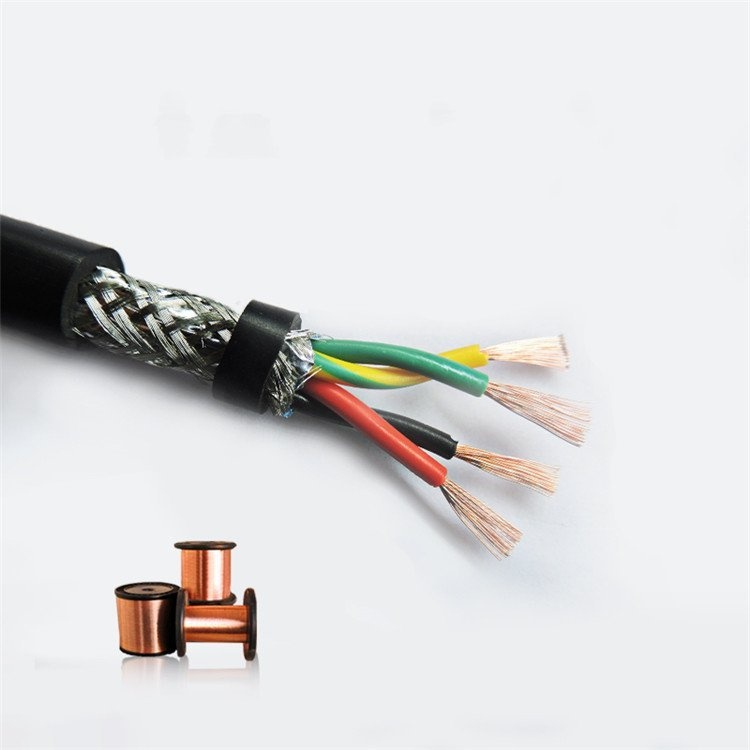
A shielded twisted pair wire is the most basic building block of industrial signal cabling: one individually foil-shielded twisted pair (two conductors + drain wire), optionally bundled with additional pairs under a common outer jacket. Unlike a multi-pair "cable" — which is designed to run between enclosures, through conduit, or in cable trays — shielded twisted pair wire is primarily used for internal equipment wiring, panel building, and short point-to-point connections where length is measured in centimetres or metres, not tens of metres.
The defining characteristics are:
- Individual foil-per-pair shielding — each pair carries its own electrostatic barrier with no shared shield volume between pairs. This is the same shielding architecture found in high-end multi-pair signal cables, scaled down to the individual pair level for internal wiring
- Compact, flexible construction — outer diameters from approximately 2.5 mm (single pair, 0.14 mm²) to 8 mm (4 pairs, 0.50 mm²), making routing through crowded wire ducts and behind DIN rail straightforward
- Drain wire for clean termination — the tinned copper drain wire in contact with the foil shield eliminates the need to fold back, solder, or clamp the delicate aluminium foil at the termination point
For runs that leave the enclosure — RS-485, CAN bus, or 4–20 mA distributed over tens of metres of conduit and cable tray — a braid-shielded multi-pair twisted pair cable is the correct construction instead. The foil-per-pair shield described here is optimised for short internal runs; over long distances the overall braid shield and the controlled characteristic impedance of a fieldbus cable do the work.
Single Pair vs Multi-Pair — Form Factor Choices
| Configuration | Typical OD Range | Supply Format | Best For |
|---|---|---|---|
| Single pair (no jacket) — foil + drain wire only | 2.5–4.5 mm | Cut lengths from reel | Individual sensor connections inside a machine frame; PCB-to-connector wiring |
| Single pair + PVC sleeve — foil shield covered by thin PVC tube | 3.0–5.0 mm | Cut lengths from reel | Slightly more mechanical protection; easier to route without foil tearing on sharp edges |
| 2-pair bundle + outer jacket | 5.0–7.5 mm | Cut lengths from reel | RS-422 full-duplex + spare; two independent sensors to the same connector |
| 3-pair bundle + outer jacket | 6.5–9.0 mm | Cut lengths from reel | Three-axis encoder feedback inside a machine enclosure |
| 4-pair bundle + outer jacket | 7.5–10.5 mm | Cut lengths from reel | Multi-channel analog input to a single PLC analog module |
Single-pair construction (no outer jacket) is the most common form factor for internal wiring — the foil shield and drain wire are sufficient protection inside a controlled enclosure environment. The outer jacket on multi-pair bundles provides mechanical protection, keeps the pairs organised, and provides a clean surface for cable glands at enclosure entry points.
Insulation Choice for Internal Wiring — PE or PVC?
Inside an equipment enclosure, the mechanical demands on the wire insulation are modest — no drag chains, no oil spray, limited UV exposure. This shifts the selection criteria toward electrical performance and termination convenience:
| Criterion | PE (Polyethylene) | PVC (Polyvinyl Chloride) |
|---|---|---|
| Capacitance | ~55 pF/m (0.50 mm²) | ~110 pF/m (0.50 mm²) |
| Signal bandwidth limit (3 m) | >10 MHz (capacitance-limited) | ~5 MHz (capacitance-limited) |
| Stripping | Clean strip — PE cuts cleanly and does not melt back during soldering | PVC can melt back from soldering iron heat if dwell time is excessive |
| Solderability | Excellent — no corrosive gases released; stable at soldering temperature | Releases HCl at soldering temperature over extended dwell — acceptable for brief contact but use fume extraction |
| Flame retardancy | Not inherently — must request FR-PE grade | Yes — PVC is self-extinguishing |
| Cold flexibility | Remains flexible to -40°C | Stiffens below 0°C but regains flexibility at room temperature |
| Cost | Lower raw material | Slightly higher |
If the equipment is destined for public-building installations (tunnels, hospitals, airports), LSZH insulation and jacket should be specified regardless of application to meet smoke and toxicity requirements.
Shield Termination Inside Enclosures
Terminating the foil shield inside a control panel enclosure requires a different approach than terminating a cable braid at a field device:
- Drain wire direct to terminal block: The tinned copper drain wire is stripped to length and landed on a dedicated shield terminal — typically an earth-referenced terminal block connected to the enclosure's functional earth busbar. This is the simplest and most common method
- Drain wire to connector shell: For connectors (D-sub, M12, M8, RJ45), the drain wire is terminated to the connector's metal shell or dedicated shield pin. This provides 360° shielding continuity through the connector if the mating half is also shielded
- Drain wire length: Keep the drain wire as short as possible between the point where the foil is stripped back and the termination point. Every millimetre of unshielded drain wire is an impedance discontinuity at high frequencies — aim for ≤30 mm exposed length
- Single-point grounding inside the enclosure: All drain wires from shielded pairs within the same enclosure should connect to a common low-impedance earth busbar. Multiple earth points inside the same enclosure can create potential differences and drive ground-loop currents
Pair Identification Systems
Inside a control panel, the person wiring it needs to quickly and unambiguously identify which pair is which — especially when multiple pairs terminate at the same PLC analog input module or multi-pin connector:
| System | How It Works | Best For |
|---|---|---|
| DIN 47100 color code | Each pair has a unique color combination: e.g. Pair 1 = white/brown, Pair 2 = white/green, Pair 3 = white/yellow, Pair 4 = white/grey | Small to medium panel builds with ≤8 pairs |
| Numbered tape / print | Each core carries a printed number (e.g. "1A", "1B", "2A", "2B") along its length | High-density panels, multi-pair cables >8 pairs, automated wire processing machines |
| Ring marking (bands) | Insulation carries printed colored bands at regular intervals in addition to the base color | When color blindness accommodation is required; machine-vision-readable identification |
Yichi can supply any of these identification systems. The default is DIN 47100 color coding for ≤8 pairs and numbered print for >8 pairs.
Why Choose Yichi for Shielded Twisted Pair Wire?
- Foil bonded to polyester — not loose-wrapped: The aluminium/polyester foil is applied longitudinally around each pair with a controlled ≥3 mm overlap and is thermally bonded to the polyester carrier. Loose foil wrapping can shift during installation, creating gaps where electrostatic coupling passes through unimpeded
- Drain wire in verified continuous contact: After foil application, each pair passes through a continuity test station that verifies the drain wire is in electrical contact with the foil along the full production length. An intermittent drain-to-foil contact — impossible to detect by visual inspection — is caught before the wire is spooled
- PE insulation as standard for signal pairs: We default to PE insulation for twisted pair wire because its electrical properties (low εr, low tan δ, stable with temperature) produce measurably cleaner signals than PVC in the same application. PVC is available as a cost-reduction option
- Short-lead custom configurations: Specify pair count, conductor size, insulation material, color code, and outer jacket type — standard items ship from stock in 3–5 days, custom-builds in 7–15 days
- Designed for the panel builder: Drain wire pre-stripped ends, sequential metre marking on the jacket, and "This End to Drive" / "This End to Motor" labelling are all available on request — small features that save hours on a large panel build