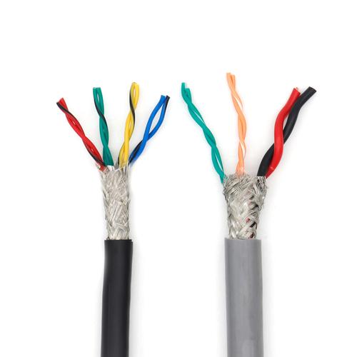
Industrial Instrumentation Cable — IEC 60092 / BS 5308 Individually and Overall Shielded Twisted Pair and Triad Multi-Pair Cable with Low Capacitance PE/PP Insulation for 4–20 mA Analog Loops, Thermocouple Extension, RTD Sensor Wiring, and Process Control Instrumentation in Petrochemical, Power Generation, and Industrial Plant Applications
Industrial, Mining & Control Cables /Instrumentation Cable

Industrial Instrumentation Cable — IEC 60092 / BS 5308 Individually and Overall Shielded Twisted Pair and Triad Multi-Pair Cable with Low Capacitance PE/PP Insulation for 4–20 mA Analog Loops, Thermocouple Extension, RTD Sensor Wiring, and Process Control Instrumentation in Petrochemical, Power Generation, and Industrial Plant Applications

Industrial instrumentation cable: IEC 60092 / BS 5308, individually and overall shielded twisted pair/triad, PE/PP insulation, low capacitance <100 pF/m. For 4-20mA loops, thermocouple, RTD, process instrumentation. 2-48 pairs, 0.5-2.5 mm². LSZH or PVC sheath. CE, RoHS, BS 5308.

Key Features

BS 5308 / IEC 60092-376 compliant — the UK and international standards for instrumentation cables used in industrial process control; BS 5308 defines the construction, screening, and electrical characteristics for twisted pair and triad instrumentation cables for the petrochemical, power generation, and process industries
Individually shielded twisted pairs or triads — each pair (2 conductors) or triad (3 conductors) has its own aluminum/polyester foil shield (100% coverage) with a tinned copper drain wire; the individual pair shielding ensures channel-to-channel isolation — the 4–20 mA signal on one pair does not interfere with the signal on an adjacent pair in the same cable
Overall shield (optional) — tinned copper braid (≥85% coverage) or aluminum/polyester foil + drain wire over the complete pair assembly; the overall shield provides additional protection against external electromagnetic interference from power cables, VFDs, and high-voltage equipment adjacent to the instrumentation cable route
Low capacitance PE (polyethylene) or PP (polypropylene) core insulation — capacitance 40–80 pF/m core-to-core for twisted pairs; low capacitance is critical for 4–20 mA analog loops because the cable capacitance, together with the loop transmitter's output impedance, determines the signal risetime and the maximum cable length for stable loop operation
0.5–2.5 mm² stranded bare copper or tinned copper conductors — 0.5 mm² for general analog instrumentation; 1.0 mm² for long-distance loops (500 m+) where conductor resistance and voltage drop become significant; 1.5–2.5 mm² for combined power + signal circuits and for thermocouple extension cable where the conductor alloy (not copper) is specified per the thermocouple type
2 to 48 pairs/triads in a single cable — 2-pair for simple point-to-point transmitter connections; 12-pair for marshalling cabinet to DCS I/O card connections; 24–48 pair for the main instrumentation trunk cable between the field junction box and the control room, carrying all the signals for one plant area in a single cable
LSZH (low smoke zero halogen) or PVC outer sheath — LSZH for offshore platforms, FPSOs, refineries, and petrochemical plants where fire safety requires halogen-free cable with low smoke and low toxicity; PVC for onshore general industrial installations where the cost premium of LSZH is not justified by the fire safety requirements
Sunlight/UV resistant LSZH or PVC sheath — the black outer sheath is UV-stabilized for outdoor cable tray installation in petrochemical plants and refineries where instrumentation cables run between field junction boxes and the control room on open-air cable trays and ladder racks

Applications

4–20 mA analog transmitter loops — individually shielded twisted pair cable from the field transmitter (pressure, temperature, level, flow) to the DCS/PLC analog input card; the cable carries the transmitter's 4–20 mA DC signal plus, in loop-powered (2-wire) configurations, the 24 V DC supply on the same pairThermocouple extension cable — twisted pair with specific conductor alloys matching the thermocouple type (Type K: Chromel/Alumel; Type J: Iron/Constantan; etc.) from the thermocouple head to the DCS thermocouple input card; the cable must be individually shielded to prevent EMI from corrupting the mV-level thermocouple signalRTD (resistance temperature detector) wiring — 3-core individually shielded triad for 3-wire RTD connections (Pt100) where the third core provides lead resistance compensation; the balanced triad construction ensures equal lead resistances for the compensation circuitMarshalling cabinet to DCS wiring — multi-pair instrumentation cable connecting the field junction box marshalling cabinet to the DCS I/O cards in the control room; a single 24-pair cable carries all the instrument signals for a process unitFieldbus and digital instrumentation — individually shielded twisted pair cable for FOUNDATION Fieldbus H1 (31.25 kbps) and PROFIBUS PA digital instrumentation networks where the same pair carries the digital communication signal and the device power supplyVibration and condition monitoring — shielded twisted pair cable for accelerometer and vibration probe connections to the machinery protection system (Bently Nevada, etc.) where the low-level mV signal requires effective shielding and the cable capacitance affects the sensor's frequency response

Technical Specifications

Standard — UK/International BS 5308-1 (Unscreened instrumentation cables); BS 5308-2 (Screened instrumentation cables — individually screened pairs with overall screen); the BS 5308 series is the definitive instrumentation cable standard in the UK and is widely referenced internationally for process plant instrumentation cable specification
Standard — Marine/Offshore IEC 60092-376 (Electrical installations in ships — cables for control and instrumentation circuits); specific requirements for offshore and marine instrumentation cable including enhanced fire performance and halogen-free construction
Standard — North America UL 2250 (Instrumentation tray cable, ITC); UL 13 (Power-limited tray cable, PLTC); the North American equivalents for instrumentation cable installed in cable trays in industrial plants per NEC Article 727
Pair/Triad Configuration — Twisted Pair Two conductors twisted together with a controlled lay length (typically 20–50 mm); the twist ensures that any magnetic field coupling from external sources induces equal voltages in both conductors — the differential input of the DCS analog input card rejects this common-mode voltage (CMRR — Common Mode Rejection Ratio, typically >80 dB at 50/60 Hz)
Pair/Triad Configuration — Triad Three conductors twisted together; used for 3-wire RTD connections where the third wire provides lead resistance compensation; the balanced triad construction maintains equal resistance in all three conductors for accurate temperature measurement
Pair Count 2, 4, 8, 12, 16, 20, 24, 36, 48 pairs/triads per cable
Conductor Material — Standard Bare copper; IEC 60228 Class 2 stranded (standard) or Class 5 flexible (for control room internal wiring); 0.5, 0.75, 1.0, 1.5, 2.5 mm²
Conductor Material — Tinned Copper For marine, offshore, and coastal installations where the salt-laden atmosphere accelerates bare copper corrosion; tinning is specified for all offshore instrumentation cable
Conductor Material — Thermocouple Extension Per IEC 60584-3 for the thermocouple type: Type K (Chromel/Alumel), Type J (Iron/Constantan), Type T (Copper/Constantan), Type E (Chromel/Constantan), Type N (Nicrosil/Nisil); the conductor alloy must produce an EMF within the standard tolerance limits
Core Insulation — PE (Standard) Solid polyethylene (PE); 75°C continuous; low dielectric constant (εᵣ = 2.3) for low capacitance (40–60 pF/m core-to-core); the standard insulation for general industrial instrumentation cable
Core Insulation — PP (Low Capacitance) Solid polypropylene (PP); 90°C; even lower dielectric constant (εᵣ = 2.2) and lower capacitance than PE; for long-distance analog loops where cable capacitance is the limiting factor for signal stability and maximum cable length
Core Insulation — XLPE (High Temperature) Cross-linked polyethylene; 90°C; for instrumentation cable routed through elevated-temperature plant areas where the 75°C PE rating would be insufficient
Core Identification — Pair Black and white (pair 1); black and red (pair 2); black and blue, etc. per BS 5308 colour coding; each pair has a unique colour combination; the pair numbering (printed on the pair or indicated by a numbered binder tape) allows the installer to identify each pair at the termination
Pair Shield — Individual (IS/OS Type) Aluminum/polyester foil (100% coverage, aluminum side in contact with the drain wire) wrapped around each pair; the foil isolates the pair from adjacent pairs and external EMI; the drain wire (7-strand tinned copper, 0.5 mm²) provides a convenient termination point for the shield at the instrument and DCS terminals
Overall Shield — Collective (IS/OS Type) Aluminum/polyester foil (100% coverage) + tinned copper braid (≥65% coverage per BS 5308-2) or tinned copper drain wire; the overall shield is applied over the complete pair assembly
Pair-to-Earth Capacitance (Typical) — PE Insulation 60–100 pF/m per pair (the capacitance between one conductor and the shield, with the other conductor also connected to the shield); lower capacitance is better — it reduces the capacitive loading on the 4–20 mA transmitter output and enables longer cable runs
Maximum DC Conductor Resistance at 20°C — Copper Per IEC 60228; 39.0 Ω/km (0.5 mm²); 26.0 Ω/km (0.75 mm²); 18.1 Ω/km (1.0 mm²); 12.1 Ω/km (1.5 mm²); 7.41 Ω/km (2.5 mm²)
Insulation Resistance at 20°C — PE ≥5 000 MΩ·km (core-to-core and core-to-shield at 500 V DC, 1 min); PE's IR is significantly higher than PVC (≥20 MΩ·km)
Test Voltage (AC) — Routine 1 000 V AC / 1 min (core-to-core, core-to-shield) per BS 5308; the test voltage reflects the 300 V AC / 500 V DC maximum operating voltage of an instrumentation circuit
Operating Voltage (Maximum) 300 V AC (rms) or 500 V DC per BS 5308; the instrumentation cable is not rated for mains voltage — it is for the extra-low-voltage (ELV) circuits of process instrumentation
Temperature — PE Insulation, PVC Sheath -30°C to +70°C (fixed)
Temperature — PE Insulation, LSZH Sheath -30°C to +70°C (fixed)
Temperature — Installation (Minimum, PVC Sheath) 0°C
Minimum Bend Radius 12× cable OD (during installation); 8× cable OD (fixed routing)
Current Rating — Analog Loop (4–20 mA) The current in a 4–20 mA analog loop is ≤20 mA — the conductor cross-section (0.5–2.5 mm²) is not the limiting factor for current; the limiting factors are the conductor DC resistance (voltage drop — the transmitter sees the loop supply voltage minus the voltage drop in the cable resistance) and the cable capacitance (signal rise time and stability)
Maximum Cable Length — 4–20 mA Loop (Estimation) The maximum cable length is limited by the loop supply voltage and the total loop resistance (cable resistance + receiver resistance). For a 24 V DC supply, a transmitter minimum operating voltage of 12 V, and a 250 Ω receiver resistor: available voltage for cable drop = 24 − 12 − (0.02 × 250) = 7.0 V; maximum cable resistance (one-way, two wires total) = 7.0 / 0.02 = 350 Ω; for 0.5 mm² cable (39 Ω/km one-way, 78 Ω/km two-wire loop resistance), maximum length = 350 / 78 = 4.5 km — in practice, the cable capacitance limit is reached first for most instrumentation cables
Flame Retardant IEC 60332-1-2 (single cable); IEC 60332-3 Cat C (bunched, on request for cable tray installations)
Halogen-Free — LSZH Sheath IEC 60754-1 (HCl <0.5%)
Certifications CE; RoHS; BS 5308 type test certificate on request; IEC 60092 type approval (marine) on request; DNV/ABS/LR on request for offshore; ISO 9001 manufactured

Detailed Description

What Is Industrial Instrumentation Cable?

Industrial instrumentation cable is a multi-pair or multi-triad cable in which each pair or triad is individually shielded with aluminum/polyester foil, and the complete pair assembly has an optional overall shield. It is the cable that connects the field instrumentation — pressure transmitters, temperature sensors, level gauges, flow meters, and control valves — to the DCS (distributed control system) or PLC analog I/O cards in the control room. It is defined by BS 5308 in the UK and is the standard instrumentation cable in petrochemical plants, refineries, power stations, and process industries worldwide.

The electrical characteristics that distinguish instrumentation cable from control cable are:

  • Individual pair shielding: Each pair must be shielded from every other pair in the same cable to prevent crosstalk between analog channels — a 4–20 mA signal on one pair must not induce a measurable signal on an adjacent pair
  • Low capacitance: The cable capacitance (40–100 pF/m core-to-core) determines the signal risetime and the maximum cable length for stable analog loop operation; a high-capacitance cable can cause the loop to oscillate or respond too slowly to process changes
  • Balanced pair construction: The twisted pair geometry ensures that any external magnetic field induces equal voltages in both conductors — the DCS differential input rejects this common-mode voltage, providing immunity to 50/60 Hz hum from adjacent power cables

Why Choose Yichi Industrial Instrumentation Cables

  • BS 5308-2 / IEC 60092-376 compliant — the definitive instrumentation cable standards: The pair construction, individual and overall shielding, core insulation material, capacitance limits, and test requirements are per the standard. The cable is not "similar to BS 5308" — it is manufactured and tested to meet the standard, and the test certificate is provided with each cable batch
  • Each pair individually shielded and tested for isolation: Every pair in every cable is foil-shielded (100% coverage) with its own drain wire. The inter-pair capacitance and cross-talk are tested on the finished cable — if one pair's signal couples into an adjacent pair at a level that exceeds the standard's limit, the cable is rejected. This is the quality control that ensures 24 analog channels on a 24-pair cable all function independently without interference
  • PE or PP insulation — low capacitance for long analog loops: The PE (εᵣ = 2.3) or PP (εᵣ = 2.2) dielectric provides 40–80 pF/m core-to-core capacitance — significantly lower than PVC (εᵣ = 4–6, capacitance 150–250 pF/m). The lower capacitance enables longer cable runs without signal degradation, reduces the capacitive loading on the transmitter output, and improves the loop's stability margin
  • LSZH or PVC sheath — select for the fire safety environment: LSZH for offshore platforms, FPSOs, refineries, and petrochemical plants where fire safety regulations mandate halogen-free cable. PVC for onshore industrial installations. Both sheaths are black, UV-stabilized, and formulated for outdoor cable tray installation
  • Thermocouple extension cable — Type K, J, T, E, N, R, S, B: The conductor alloy is certified to the thermocouple EMF standard (IEC 60584-1). The cable is supplied with a calibration certificate stating the EMF deviation from the standard table at the production test temperature. The individual pair shielding protects the mV-level thermocouple signal from EMI in the electrically noisy plant environment

Product Inquiry

Product: Industrial Instrumentation Cable — IEC 60092 / BS 5308 Individually and Overall Shielded Twisted Pair and Triad Multi-Pair Cable with Low Capacitance PE/PP Insulation for 4–20 mA Analog Loops, Thermocouple Extension, RTD Sensor Wiring, and Process Control Instrumentation in Petrochemical, Power Generation, and Industrial Plant Applications

Add technical specifications (optional)

The more detail you provide, the faster and more accurate our quotation.

No file chosen

PDF, Office, image or CAD file — up to 5 MB

Need Help?

Certifications

ISO 9001
Quality
CE
European
RoHS
Environmental
TÜV
Certification

Need a Quote for This Product?

Send us your requirements and receive a detailed quotation within 24 hours.