Detailed Description
What Is a Network Composite Reeling Cable?
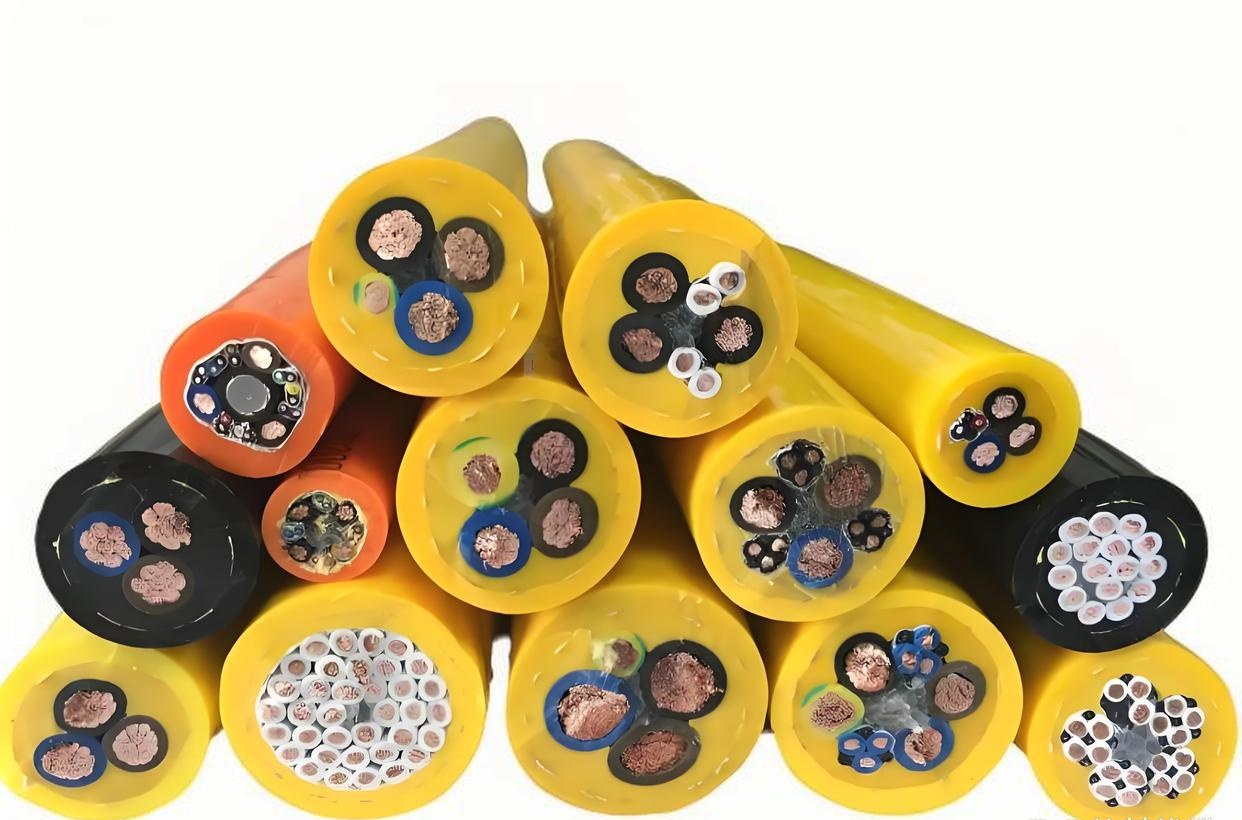
A network composite reeling cable is a single-drum cable assembly that combines power conductors, Ethernet data pairs, fiber optic elements, and control cores into one integrated reeling cable — eliminating the need for multiple separate cable drums on cranes, hoists, stacker/reclaimers, and heavy mobile equipment.
In a traditional crane installation, power, control, Ethernet, and CCTV each require a separate reel with its own cable, drum, slip ring, and maintenance schedule. Four reels means four times the space, four times the slip ring maintenance, and four times the potential failure points. A network composite reeling cable consolidates these functions into a single cable on a single drum — one cable pull, one slip ring assembly (power + fiber rotary joint + Ethernet slip ring), one maintenance schedule.
The challenge is that each element type — power, data, fiber — has different mechanical requirements. Power conductors need to survive sustained drum compression. Ethernet pairs need to maintain 100 Ω impedance and low crosstalk through millions of flex cycles. Optical fibers must not experience micro-bending or attenuation increase under load. The composite reeling cable is a mechanical and electrical integration problem, and the cable design must satisfy all constraints simultaneously.
Why Composite Reeling Instead of Separate Cables?
| Consideration | Separate Cables (4 Drums) | Composite Reeling Cable (1 Drum) |
|---|---|---|
| Drum count | 4 (power, control, Ethernet, fiber/CCTV) | 1 |
| Slip ring assemblies | 4 separate; 4 maintenance schedules | 1 integrated; 1 maintenance point |
| Crane space requirement | 4 drum positions on boom or bridge | 1 drum position |
| Cable management | 4 cables from drums to moving trolley/hoist | 1 cable bundle |
| Installation cost | 4× cable pulls, 4× termination, 4× testing | 1× cable pull, 1× termination, 1× testing |
| Failure points | 4 × (cable + drum + slip ring) | 1 × (cable + drum + slip ring) — fewer but critical |
| Replacement complexity | Replace one function at a time | Full cable replacement, but simpler logistics |
For new crane builds, the composite approach is the modern standard — it reduces crane weight, simplifies commissioning, and standardizes cable management. For retrofit projects, a composite reeling cable often replaces 3–4 aging separate cables, freeing drum positions for additional functions.
Mixed-Element Configurations — What Goes Into the Cable?
Power + Ethernet
- Example: 4G16 mm² (power) + CAT6 4-pair SFTP (Ethernet)
- For crane HMI panels, IP cameras, and I/O blocks on the moving trolley that need both motor power and Gigabit Ethernet
- Power cores carry 400 V three-phase motor and auxiliary power; Ethernet carries PROFINET or EtherNet/IP control traffic
Power + Fiber + Ethernet
- Example: 4G35 mm² (power) + 12-fiber single-mode (data backbone) + CAT5e 4-pair SFTP (Ethernet)
- Fiber for crane CMS (condition monitoring system), remote diagnostics, and video backhaul
- Ethernet for local device network on the moving structure
- Fibers in gel-filled stainless steel loose tube — crush-resistant to 4 000 N/100 mm
Full Composite — Power + Ethernet + Fiber + Control + Coax
- Example: 3×50 mm² + 3×35 mm² + 3G25 mm² (power) + 24×1.5 mm² (control) + CAT6 4-pair SFTP (Ethernet) + 24-fiber SM (fiber) + RG-59 coax (CCTV)
- Complete crane connectivity in a single cable
- Used on large STS cranes with full automation, remote operation, and multiple camera systems
Fiber Optic Performance Under Reeling Conditions
Optical fiber in a reeling cable must maintain its attenuation budget through continuous winding and unwinding:
- Micro-bending control: The fiber loose tube is stranded with a controlled excess fiber length (EFL) of 0.1–0.3% — enough to prevent strain during bending, not enough to cause micro-bend loss
- Crush protection: Stainless steel loose tube rated to 4 000 N/100 mm flat-plate crush; gel filling prevents moisture ingress
- Attenuation stability: Insertion loss change <0.1 dB at 1 550 nm after 200 000 reeling cycles — verified by OTDR before and after cycling
- Fiber types: G.652D single-mode for long-distance backhaul; G.651 or OM3/OM4 multi-mode for shorter intra-crane links with lower-cost transceivers
- Connectorization: Fibers terminated in ST, SC, LC, or E-2000 connectors at the slip ring; field-connectorizable on request
Ethernet Performance — Reeling vs Drag Chain
Ethernet pairs in a reeling cable face different stress than those in a drag chain:
| Stress Factor | Drag Chain Ethernet | Reeling Drum Ethernet |
|---|---|---|
| Primary motion | Bending in one plane | Bending + multi-layer compression |
| Bend radius | 10–15× OD | 10–20× OD (drum dependent) |
| Sustained compression | None | Inner layers under continuous load |
| Flex cycle count | >5 000 000 | >200 000 (but with compression) |
| Failure mode | Conductor fatigue from repeated bending | Insulation deformation + shield discontinuity from compression |
The Ethernet pairs in a composite reeling cable are positioned in the outer layers of the core assembly, where bend radius is larger and compression from upper layers is lower. Data and fiber elements are never placed in the center of the cable (the highest compression zone) — the center is reserved for the steel tensile core or, in cables without one, for a compression-resistant filler element.
Drum Installation Requirements
- D/d ratio: Minimum 10:1 for the composite cable OD; 15:1 for rated reeling life. The D/d ratio applies to the drum core diameter, not the flange diameter
- Layer management: The first winding layer must be tight and gapless — gaps in layer 1 propagate through all subsequent layers and concentrate compressive stress on the data elements in the outer layers
- Slip ring compatibility: Ensure the slip ring assembly supports all signal types in the cable — power (to 1 kV), Ethernet (to 1 Gbps), fiber (SM or MM), and coaxial (if included). The slip ring is as critical as the cable for composite performance
- Cable anchorage: The drum-end cable termination must be mechanically anchored to carry full cable tension. The electrical and optical terminations must not bear any mechanical load
Why Choose Yichi Network Composite Reeling Cables
- Integrated engineering — power + data + fiber in one cable: We engineer the complete core assembly with proper lay lengths, compression-resistant fillers, and correct radial positioning to ensure every element type — power, Ethernet, fiber, control — performs through the rated reeling life
- Fiber performance verified by OTDR: Every fiber in every production batch is tested on an OTDR before and after simulated reel cycling. Insertion loss change must be <0.3 dB at rated cycles — if a fiber fails this test, the cable is rejected
- Ethernet electrical performance maintained: CAT5e/CAT6 pairs are tested for wiremap, NEXT, return loss, and insertion loss after reeling cycle testing. The impedance and crosstalk specifications must hold through the full rated cycle count
- Compression-validated construction: Core stranding is tested under simulated 10-layer drum compression. Conductor cross-section circularity, insulation thickness, and fiber attenuation are measured before and after — all must remain within specification
- Application engineering support: Send us your drum dimensions, required cable length, signal types, and operating environment — we verify D/d compatibility, recommend the optimal core layout, and specify the correct slip ring interface