Detailed Description
What Is Wind Energy Specialty Cable?
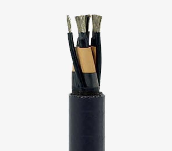
Wind energy specialty cable is the collective term for the control, signal, data communication, fiber optic, and lightning protection cables that serve the non-power electrical functions inside a wind turbine. While the FDEH power cables carry the generated electricity from the generator to the tower base, the specialty cables are the nervous system of the turbine — the sensor cables that detect a bearing defect before it becomes a catastrophic failure, the data cables that allow the turbine controller to adjust the blade pitch for optimal energy capture, the fiber optic cables that transmit blade load data to the condition monitoring system, and the lightning protection cables that safely conduct a 200 kA lightning strike from the blade tip to the ground without damaging the turbine's electronics.
These cables share the same environmental conditions as the power cables — vibration, oil mist, temperature cycling, torsion — but have additional requirements: electromagnetic compatibility (the ability to transmit clean signals in the electrically noisy nacelle environment), characteristic impedance control (for data bus cables to maintain signal integrity), and fiber protection (for optical cables to maintain attenuation budget under mechanical stress).
The Nacelle EMI Environment — Why Shielding Is Mandatory
A modern multi-megawatt wind turbine nacelle contains a power converter that switches hundreds of amperes at 2–16 kHz using IGBT (insulated-gate bipolar transistor) semiconductors. The fast switching edges (typically 50–500 ns rise time) generate broadband electromagnetic interference from the power converter's switching frequency up to tens of megahertz, radiating from the converter cabinet, the generator cables, and the tower down conductors.
An unshielded signal cable running within a meter of a generator power cable will have tens to hundreds of millivolts of EMI coupled into the signal conductors — enough to corrupt a millivolt-level vibration sensor signal or cause bit errors on a CAN bus communication link. The shielding design for wind turbine specialty cables addresses this:
| Shielding Layer | Covers | Attenuates |
|---|---|---|
| Foil per pair (100%) | Individual signal pair | High-frequency (>10 MHz) electric field coupling between adjacent pairs; ensures channel-to-channel isolation for multi-channel sensor cables |
| Overall braid (≥85%) | Entire core assembly | Low-to-medium frequency (<10 MHz) magnetic field coupling from the power conductors; provides the common ground reference for all signal pairs |
| Cable routing (physical separation) | Installation | Spatial separation reduces the magnetic field strength by 1/r²; signal and data cables are routed separately from the power cables in the nacelle cable tray |
For CAN bus, PROFINET, and EtherCAT cables operating in the nacelle, the shield transfer impedance (Z_T) is the key specification. The cable's Z_T at the frequency range of the power converter EMI (2–20 MHz) determines how much of the external EMI field penetrates the shield and couples into the data pairs. For wind turbine data cables, Z_T should be ≤10 mΩ/m at 10 MHz — achieved through the combination of dense braid coverage (≥85%) and optimized braid angle (30–50°).
Why Choose Yichi Wind Energy Specialty Cables
- Complete turbine specialty cable solution: One manufacturer for the full suite of wind turbine control, signal, data, fiber, and lightning protection cables — consistent quality, single-source documentation, coordinated cable OD and mechanical characteristics for the turbine cable management system design
- Shielding engineered for the nacelle EMI environment: The foil + braid shield construction is tested for transfer impedance across the frequency range of interest; the shield is not just "present" — it is verified to provide the attenuation required for clean signal transmission adjacent to the generator and converter power cables
- Torsion-rated for service loop cables: Cables that cross the rotating interfaces (nacelle-to-hub pitch cables, nacelle-to-tower loop cables) are designed and tested for the torsion duty of that specific location — ±150°/m, >10 000 cycles, with continuous electrical monitoring
- CAN bus, PROFINET, EtherCAT — impedance-matched and tested: The characteristic impedance (120 Ω for CAN, 100 Ω for Ethernet) is controlled through the cable design and verified by TDR (time-domain reflectometry) measurement on every production batch. An impedance mismatch at the cable or connector creates signal reflections that increase bit error rate — particularly critical in the long bus lengths (20–40 m) typical in multi-megawatt turbines
- Fiber optic integration — power + signal + fiber in one cable: Fiber elements can be integrated with copper control and signal cores in a single composite cable, reducing the number of separate cables routed through the nacelle. The fiber loose tube is designed for the same torsion and flex duty as the copper elements, and the fiber attenuation is verified before and after mechanical testing
- Lightning protection cable sized per IEC 62305: The lightning down conductor cross-section (50–120 mm²) is calculated per IEC 62305-1 for the turbine's lightning protection level (LPL I–IV). The cable routing minimizes inductance (L × di/dt voltage drop during the lightning current) by following the shortest, straightest path from the blade receptor to the foundation earth electrode