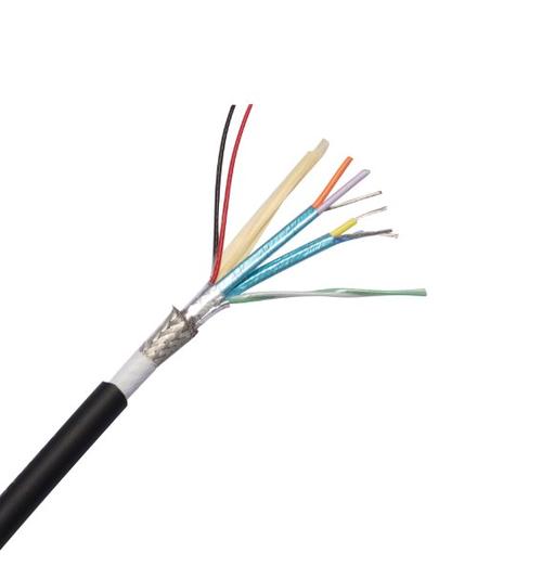
Detailed Description
What Is a CAN Bus Communication Cable?
CAN (Controller Area Network) bus is a differential serial communication protocol originally developed by Bosch for automotive applications and now the dominant fieldbus in vehicles, industrial automation, marine electronics, and medical equipment. The CAN bus cable is the physical transmission medium — a single twisted pair with a characteristic impedance of 120 Ω, terminated at each end of the bus with a 120 Ω resistor.
The cable carries two signals: CAN_H and CAN_L, which are complementary — when CAN_H goes high (toward 3.5 V), CAN_L goes low (toward 1.5 V). The differential receiver at each node reads the voltage difference between the two lines, providing inherent common-mode noise rejection. The dominant (logic 0) and recessive (logic 1) states are defined by this differential voltage, with the recessive state being 0 V differential (both lines at approximately 2.5 V).
The simplicity of CAN bus — two wires plus a shield — is its strength. A single twisted pair carries engine RPM, coolant temperature, transmission gear, wheel speed, brake pressure, and diagnostic data simultaneously at 250–500 kbps, prioritized by message identifier (lower ID = higher priority, resolving bus contention without a master controller).
CAN Bus Cable — Impedance, Termination, and Bus Length
| Parameter | Value | Why It Matters |
|---|---|---|
| Characteristic impedance | 120 Ω | Must match the termination resistors at each bus end. Mismatch causes signal reflections that corrupt the bit timing |
| Termination | 120 Ω resistor between CAN_H and CAN_L at each physical end of the bus | Absorbs the signal energy at the bus ends; without termination, the signal reflects, causing errors |
| Maximum stub length | 0.3 m at 1 Mbps | The drop cable from the bus trunk to each node must be short to avoid impedance discontinuities |
| Bus length vs data rate | 40 m at 1 Mbps; 500 m at 125 kbps | The CAN bit timing limits the maximum bus length: the signal must propagate to the furthest node and back within one bit time |
CAN Bus Protocols — One Cable, Many Languages
| Protocol | Standard | Data Rate | Application | Cable Colour Convention |
|---|---|---|---|---|
| CAN 2.0A/B | ISO 11898-2 | Up to 1 Mbps | Base CAN protocol — the foundation for all higher-layer protocols | No standard colour |
| CANopen | CiA 301 | 125–1 000 kbps | Industrial automation — drives, I/O, encoders | Purple jacket, white/brown pair |
| DeviceNet | ODVA | 125–500 kbps | Factory automation — sensors, actuators, motor starters | Purple jacket (trunk), yellow (drop) |
| SAE J1939 | SAE | 250 kbps | Heavy-duty vehicles — engine, transmission, brakes, body | No standard colour; typically black automotive cable |
| NMEA 2000 | NMEA | 250 kbps | Marine electronics — GPS, depth, wind, engine, autopilot | Blue jacket (backbone), light blue (drop) |
| CAN FD | ISO 11898-1 | Up to 8 Mbps | Higher data rate for firmware updates, diagnostics, and data-intensive sensors | Same cable as CAN 2.0 — the bus can mix CAN 2.0 and CAN FD nodes |
Application Analysis
- SAE J1939 vehicle networks: A diesel truck's engine ECU, transmission controller, ABS module, instrument cluster, and body controller all communicate on a single CAN bus at 250 kbps — the twisted pair cable runs through the vehicle chassis wiring harness alongside high-current motor and lighting cables
- CANopen machine automation: A packaging machine's PLC communicates with 15 servo drives, 4 I/O blocks, and 2 encoder modules on a CANopen bus at 500 kbps — the purple CANopen cable is instantly recognizable in the control cabinet trunking
- DeviceNet factory networks: A conveyor line with distributed motor starters, proximity sensors, and pushbutton stations networked on DeviceNet at 125 kbps — the trunk/drop cable topology with sealed M12 connectors survives the factory floor
- NMEA 2000 marine electronics: A yacht's chartplotter, GPS, depth sounder, wind sensor, engine gateway, and autopilot share navigation and engine data on a single NMEA 2000 CAN bus backbone
Why Choose Yichi for CAN Bus Cables
- 120 Ω impedance verified by TDR on every production length: The characteristic impedance of the cable must be 120 Ω for the bus to work. Yichi measures it with a time-domain reflectometer (TDR) on each production length — not estimated from conductor geometry
- Controlled twist lay length for consistent impedance: The twist rate of the CAN_H/CAN_L pair determines the cable's impedance. Yichi controls the lay length to within ±2 mm — a variation that keeps the impedance within the 120 Ω ±10 Ω specification
- PUR jacket for machine and vehicle duty — PVC for fixed indoor: Select the jacket material that matches the installation environment. PUR for drag chains, robot arms, engine bays, and outdoor vehicle wiring; PVC for indoor control cabinets and fixed cable trays
- Shield drain wire for CAN_GND reference: The shield drain wire connects to the CAN_GND (ground reference) pin at the bus connector, providing the common-mode voltage reference that all CAN nodes share. Without this, nodes with different ground potentials cannot communicate reliably
- Factory-direct for OEM and system integrator quantities: Vehicle OEMs, machine builders, and marine electronics installers specifying CAN bus cable by the kilometre — Yichi provides consistent 120 Ω impedance and competitive volume pricing