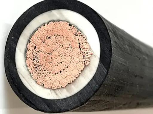
FDEH Wind Turbine Power Cable — Flexible EPR Insulated CR/CPE Sheathed Torsion-Resistant 0.6/1 kV to 1.8/3 kV Wind Turbine Nacelle and Tower Cable with Class 5 Tinned Copper Conductor, EMC Shielding, and Cold-Flex Rating to -40°C for Pitch, Yaw, Generator, and Tower Down Conductor Applications
EV Charging & Renewable Energy Cables /Wind Turbine Cable

FDEH Wind Turbine Power Cable — Flexible EPR Insulated CR/CPE Sheathed Torsion-Resistant 0.6/1 kV to 1.8/3 kV Wind Turbine Nacelle and Tower Cable with Class 5 Tinned Copper Conductor, EMC Shielding, and Cold-Flex Rating to -40°C for Pitch, Yaw, Generator, and Tower Down Conductor Applications

FDEH wind turbine power cable: EPR insulated, CR/CPE sheathed, 0.6/1kV to 1.8/3kV. Class 5 tinned copper 1.5–240 mm², optional EMC shield. Torsion resistant ±150°/m, cold-flex -40°C. For wind turbine nacelle, pitch, yaw, generator, tower connections. Oil, UV, ozone, salt spray resistant. CE, RoHS.

Key Features

FDEH type designation — the Chinese standard wind turbine cable (风力发电用电缆 Fēnglì Fādiàn Diànlǎn) designed for the extreme mechanical and environmental conditions inside a wind turbine nacelle and tower: continuous vibration, torsion in the cable loop between nacelle and tower, oil mist from the gearbox, and temperature cycling from -40°C winter shutdown to +70°C summer full-load operation
EPR (ethylene propylene rubber) core insulation — selected for wind turbine cable because EPR combines high dielectric strength with the flexibility, torsion resistance, and compression recovery that the cable loop between the rotating nacelle and the fixed tower demands; PVC and XLPE are not suitable for the torsion duty
CR (neoprene) or CPE (chlorinated polyethylene) outer sheath — oil-resistant (gearbox oil mist, hydraulic oil, grease), weather-resistant (tower interior can experience condensation and humidity), UV-resistant for the tower base section exposed to daylight through the access door, and flame-retardant for fire safety inside the enclosed nacelle space
Class 5 flexible tinned copper conductor — the tinning protects against corrosion in the condensing humidity environment inside the nacelle and tower; the fine stranding (Class 5) provides the flexibility to form the service loop between nacelle and tower that must accommodate the yaw rotation of the nacelle (typically ±3 full rotations, 1 080°)
Torsion rated ±150° per meter — the cable service loop in the tower top section experiences torsion around its longitudinal axis as the nacelle yaws to face the wind; the cable construction (lay length, filler design, conductor stranding) is engineered for torsional freedom without conductor fatigue or insulation damage
Optional EMC (electromagnetic compatibility) shield — tinned copper braid (≥85% coverage) over the core assembly or individual shielded pairs; wind turbine power converters (IGBT-based) generate high-frequency EMI that can interfere with the turbine's control and communication systems; shielded power cables reduce radiated EMI from the power conductors
0.6/1 kV for generator and auxiliary power; 1.8/3 kV for the generator-to-converter power connection — the two standard voltage classes for wind turbine internal power cabling per the turbine manufacturer's electrical specification
Cold-flex rated to -40°C — the cable must remain flexible and installable during winter maintenance when the turbine is stopped and the nacelle interior temperature equals the outside ambient; PVC cable would be glass-brittle; EPR/CR cable remains flexible

Applications

Wind turbine nacelle internal power cabling — cables from the generator terminals to the power converter cabinet, and from the converter to the tower down conductor connection point; the cables are routed through the confined, oil-mist-exposed nacelle interior with multiple bends and supportsWind turbine pitch system cabling — cables from the pitch control cabinet in the nacelle to the pitch motors in the rotating hub; the cable passes through the slip ring or service loop that accommodates the continuous blade pitch rotation; torsion-rated cable construction is essentialWind turbine yaw system cabling — power and control cables for the yaw drive motors that rotate the nacelle to face the wind; the cables experience vibration from the yaw gear drive and are exposed to grease and oil from the yaw bearing lubricationTower down conductor — the main power cables running vertically from the nacelle to the tower base switchgear; the cables are supported at intervals (typically every 1.5–3 m) in the tower cable management system and experience the full nacelle yaw rotation as a torsional input at the top cable terminationWind turbine auxiliary power — cables for auxiliary systems inside the nacelle: cooling fans, oil pumps, heaters, lighting, and service sockets; typically lower current but must meet the same environmental specification as the main power cablesOffshore wind turbine — cables for offshore turbines with enhanced corrosion protection (tinned copper conductor, CR sheath with salt spray resistance) and, for the submerged tower section, additional water-blocking construction to prevent water migration along the cable if the tower base is flooded

Technical Specifications

Type Designation FDEH (Chinese standard wind turbine cable); compliance with the mechanical and electrical requirements of GB/T 29631 (Chinese national standard for wind turbine cables) and IEC 60502-1 for the 0.6/1 kV power cable electrical parameters
Rated Voltage — Power U₀/U = 0.6/1 kV (generator auxiliary, yaw, pitch, tower auxiliary); 1.8/3 kV (generator-to-converter main power connection, on request)
Rated Voltage — Control / Signal (If Combined) 300/500 V; control and signal cores may be integrated with power cores in a composite wind turbine cable
Conductor Material Tinned copper; IEC 60228 Class 5 flexible stranded; tinning is specified to prevent copper corrosion in the condensing humidity environment inside the nacelle where the temperature cycles daily between ambient night-time low and daytime solar-heated high, creating condensation on all metal surfaces
Conductor Cross-Sections — Power 1.5, 2.5, 4, 6, 10, 16, 25, 35, 50, 70, 95, 120, 150, 185, 240 mm²
Conductor Cross-Sections — Control (Optional) 0.75, 1.0, 1.5, 2.5 mm²; numbered or color coded; up to 36 control cores in a composite cable with power cores
Core Insulation — EPR Ethylene propylene rubber; rated 90°C continuous; 250°C short-circuit; the insulation is formulated for the combined electrical and mechanical duty of wind turbine service — dielectric strength, flexibility, torsion resistance, and oil resistance
Core Identification — Power Color coded: black, red, blue (L1/L2/L3); green-yellow (PE); numbered on request per the turbine manufacturer's wiring specification
Core Identification — Control Numbered black cores per VDE 0293 or color coded per DIN 47100
Core Assembly Concentric stranding with special lay length and anti-torsion filler elements; the lay length is selected to balance bending flexibility with torsional freedom — the cable must bend in the nacelle cable tray and twist in the service loop without the individual cores shifting position or the conductor strands accumulating fatigue damage
Anti-Torsion Filler Elements PU (polyurethane) rods or aramid-reinforced profile fillers in the core interstices; the fillers provide elastic recovery force that returns the cable to its neutral position when the torsional force is removed (when the nacelle yaws back to its neutral position)
Tensile Reinforcement (Optional) Aramid yarn (Kevlar) central strength member; carries the cable's own weight in the tower vertical section, reducing the tensile load on the copper conductors
Inner Sheath CR or CPE rubber; provides additional mechanical protection between the core assembly and the outer sheath or shield
EMC Shield (Optional) Tinned copper braid; ≥85% coverage; applied over the inner sheath; provides a low-impedance return path for common-mode currents from the power converter and reduces radiated EMI that could interfere with the turbine's control, communication, and condition monitoring systems
Outer Sheath — CR Polychloroprene rubber (neoprene); Shore A 60–70; black; the standard sheath for wind turbine cables because of its balanced oil, weather, flame, and mechanical resistance properties
Outer Sheath — CPE (Cold-Climate) Chlorinated polyethylene rubber; Shore A 60–70; black; for wind turbines in Arctic and sub-Arctic locations where the CR sheath may stiffen below -30°C; CPE retains flexibility to -50°C
Sheath Thickness 1.5–3.0 mm depending on the cable diameter; the sheath thickness is engineered for the mechanical environment — abrasion against the nacelle structure, oil mist exposure, and handling during turbine maintenance
Maximum DC Conductor Resistance at 20°C — Tinned Copper Per IEC 60228 Class 5; 13.7 Ω/km (1.5 mm²) to 0.0802 Ω/km (240 mm²)
Insulation Resistance at 20°C — EPR ≥1 000 MΩ·km (at 500 V DC, 1 min)
Test Voltage (AC) — 0.6/1 kV 3 500 V AC / 5 min (routine, finished cable) per IEC 60502-1
Test Voltage (AC) — 1.8/3 kV 6 500 V AC / 5 min (routine, finished cable) per IEC 60502-2
Temperature Range — Flexing / Moving -40°C to +80°C (CR sheath); -50°C to +80°C (CPE sheath); the cable must flex when the turbine is operational and when maintenance is performed in winter conditions
Temperature Range — Fixed -50°C to +90°C (CR); -50°C to +90°C (CPE)
Torsion Rating ±150° per meter of cable length; the torsion test per the turbine manufacturer's specification or per GB/T 29631 involves cycling the cable at ±150°/m for a specified number of cycles (typically >10 000) while monitoring conductor resistance and insulation integrity
Minimum Bend Radius — Flexing 6× cable OD (occasional flexing during installation and maintenance)
Minimum Bend Radius — Fixed Routing 4× cable OD (fixed routing in the nacelle cable tray)
Oil Resistance — CR/CPE Sheath IEC 60811-404; the cable operates in an environment saturated with gearbox oil mist, hydraulic oil, and grease; the sheath must not soften, swell, or lose mechanical strength after prolonged oil exposure
Weather / UV Resistance Excellent — carbon black reinforced CR/CPE is inherently UV-stable for the tower base section and the yaw deck area that may be exposed to daylight
Ozone Resistance Excellent — CR/CPE is ozone-resistant; important in the high-voltage environment near the generator and converter where corona discharge can generate ozone
Salt Spray Resistance (Offshore) IEC 60068-2-52; enhanced grade CR/CPE compound tested for offshore wind turbine service; the salt-laden marine atmosphere accelerates corrosion of unprotected copper and steel components
Flame Retardant IEC 60332-1-2; CR/CPE self-extinguishing; fire safety in the enclosed nacelle space is critical — a cable fire in a nacelle 80–150 m above ground is a catastrophic event that can destroy the turbine
Halogen-Free (CPE Sheath) IEC 60754-1; CPE is halogen-free; CR contains chlorine but at a lower percentage than PVC and the combustion products are less acidic
Certifications CE, RoHS; GB/T 29631 type testing on request; ISO 9001 manufactured; turbine manufacturer-specific qualification testing available per the manufacturer's cable specification

Detailed Description

What Is FDEH Wind Turbine Power Cable?

FDEH is the Chinese designation for wind turbine power cable (风力发电电缆 Fēnglì Fādiàn Diànlǎn — the characters F, D, E, H encode the cable type per the Chinese cable designation system). It is a flexible EPR-insulated, CR/CPE-sheathed power cable designed specifically for the extreme mechanical and environmental conditions inside a wind turbine nacelle and tower.

The wind turbine environment is uniquely demanding: the nacelle sits 80–150 meters above ground, rotating to face the wind. The cables inside the nacelle are exposed to continuous vibration from the gearbox and generator, oil mist from the gearbox lubrication system, temperature cycling from -40°C to +70°C, and electromagnetic interference from the IGBT-based power converter that conditions the generator output to grid-synchronous power. The cable service loop between the nacelle and the tower experiences torsion — ±150° per meter — as the nacelle yaws to face changing wind directions, cycling hundreds of times per day over the turbine's 20–25 year design life.

A standard power cable installed in this environment would fail within months: PVC insulation embrittles from oil exposure and low-temperature cycling; XLPE insulation lacks the torsion flexibility that EPR provides; bare copper conductor corrodes from condensation; a PVC sheath cracks from ozone generated by the high-voltage generator and converter. The FDEH cable construction — EPR insulation, CR/CPE sheath, tinned copper conductor, anti-torsion stranding — is the engineered solution for this environment.

The Torsion Problem — Why Wind Turbine Cable Is Different

Torsion — twisting around the cable's longitudinal axis — is the mechanical stress that distinguishes wind turbine cable from all other industrial flexible cables. A drag chain cable bends in one plane. A robot cable bends and twists at the joints. A wind turbine cable experiences pure torsion in the service loop at the tower top, where the cable connects the fixed tower wiring to the rotating nacelle.

When a standard stranded cable is twisted, the helical lay of the conductors tightens on one side of the twist and loosens on the other — the conductors on the tight side experience compression (buckling), and those on the loose side experience tension (necking). Over thousands of torsion cycles, this alternating compression/tension fatigues the copper strands and eventually breaks them.

Wind turbine cable addresses torsion through three design elements:

  1. Controlled lay length: The core stranding lay length is shorter than a standard flexible cable — typically 8–12× the core diameter versus 12–16× for standard — to minimize the relative movement between strands during torsion
  2. Anti-torsion filler elements: PU or aramid-reinforced rods in the core interstices act as elastic springs — they store energy when the cable is twisted and release it when the twist is removed, returning the cable to its neutral position and reducing the mechanical work that the copper conductors must absorb
  3. EPR insulation: EPR's rubber-like elasticity allows the insulation to deform elastically with the conductor during torsion and recover without permanent deformation or delamination from the conductor surface

Why Choose Yichi FDEH Wind Turbine Power Cables

  • EPR insulation as standard — the correct material for wind turbine duty: EPR is the only insulation that provides the combination of torsion flexibility, oil resistance, and cold-flex performance that wind turbine service demands. PVC and XLPE are not suitable for torsion applications and should not be specified for wind turbine nacelle cabling
  • Torsion-rated construction verified by type testing: The cable's torsion performance is verified on a torsion test machine — ±150° per meter, >10 000 cycles, with continuous monitoring of conductor resistance and insulation integrity. The test acceptance criteria: zero conductor breaks, <10% increase in resistance, no insulation or sheath cracking
  • Anti-torsion filler system engineered for the cable diameter: The filler type, size, and placement in the core assembly are selected for each cable design based on the core configuration, overall diameter, and expected torsion angle — not a generic filler applied to all cable sizes
  • CR and CPE sheath options — select for your installation climate: CR for standard onshore wind turbines; CPE for Arctic/sub-Arctic locations where winter temperatures below -30°C are expected. The sheath material selection matches the turbine site's minimum operating temperature
  • EMC shield option for converter-to-generator cables: The power converter generates high-frequency EMI; a shielded power cable provides a low-impedance common-mode return path and reduces radiated EMI into the turbine's control, communication, and condition monitoring systems
  • Turbine manufacturer specification compliance: We manufacture to the individual wind turbine manufacturer's cable specification — the core count, cross-section, color code, shield configuration, and mechanical test requirements defined by the turbine OEM for each cable position in the turbine

Product Inquiry

Product: FDEH Wind Turbine Power Cable — Flexible EPR Insulated CR/CPE Sheathed Torsion-Resistant 0.6/1 kV to 1.8/3 kV Wind Turbine Nacelle and Tower Cable with Class 5 Tinned Copper Conductor, EMC Shielding, and Cold-Flex Rating to -40°C for Pitch, Yaw, Generator, and Tower Down Conductor Applications

Add technical specifications (optional)

The more detail you provide, the faster and more accurate our quotation.

No file chosen

PDF, Office, image or CAD file — up to 5 MB

Need Help?

Certifications

ISO 9001
Quality
CE
European
RoHS
Environmental
TÜV
Certification

Need a Quote for This Product?

Send us your requirements and receive a detailed quotation within 24 hours.