Detailed Description
What Is Armoured Cable (SWA/STA)?
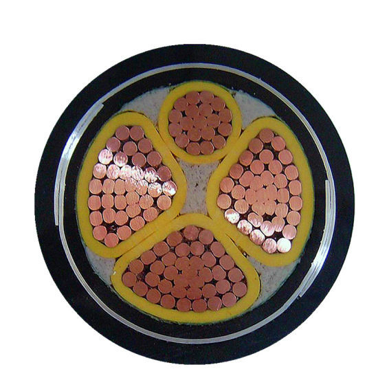
Armoured cable is a power cable with a layer of galvanized steel wires (SWA — Steel Wire Armour) or steel tapes (STA — Steel Tape Armour) applied over the insulated core assembly, providing mechanical protection that enables the cable to be installed in environments where it would otherwise be damaged: buried directly in soil, pulled through underground ducts, run across factory floors, or clipped to external walls. The armour is the cable's mechanical defence — it stops a spade from cutting through to the conductors during gardening, prevents a rat from gnawing into the copper, and survives the weight of backfill soil and the traffic above a buried cable route.
In the IEC world, SWA and STA are defined by IEC 60502-1, which specifies the armour wire diameter and tape thickness for each standard cable size. The cable designation codes indicate the armour type:
- SWA: Steel Wire Armour (e.g., YJV22 — XLPE insulated, PVC sheathed, steel wire armoured; or VV22 — PVC insulated, PVC sheathed, steel wire armoured)
- STA: Steel Tape Armour (e.g., YJV32 — XLPE insulated, PVC sheathed, steel tape armoured)
SWA vs STA — Which Armour for Which Application?
| Parameter | SWA (Steel Wire Armour) | STA (Steel Tape Armour) |
|---|---|---|
| Armour construction | Round or flat galvanized steel wires, helical lay | Two galvanized steel tapes, helical lay with overlap |
| Tensile strength | High — the steel wires carry significant tensile load | Low — tapes provide minimal tensile strength |
| Crush resistance | Good — the wires distribute the crush load across multiple points | Excellent — the continuous tape surface provides uniform crush resistance |
| Impact resistance | Good | Good |
| Rodent protection | Excellent — rodents cannot gnaw through steel wires | Good — steel tapes provide a continuous barrier, but determined rodents can peel back the tape edge at the overlap |
| Flexibility | Moderate — the helical wire armour is flexible but heavier | Better — lighter and slightly more flexible than SWA |
| Weight | Heavier (the steel wires add significant weight) | Lighter |
| Cost | Higher (more steel) | Lower |
| Earth continuity | Larger steel cross-section → lower armour resistance → better earth fault path | Smaller steel cross-section → higher armour resistance → may require a separate copper earth conductor for earth fault loop impedance compliance |
| Best for | Direct burial, underground ducts, long cable runs, locations with ground movement, rodent-prone areas | Indoor industrial cable tray, short underground ducts, locations where crush is the primary hazard and weight is a concern |
SWA is the default specification for any cable that goes underground or outdoors. The SWA's tensile strength is essential for buried cables — the ground settles, freezes and thaws, and is subject to excavation and construction activity. The tensile capability of the steel wire armour prevents the copper conductors from being stretched or broken by ground movement. For above-ground industrial installation where mechanical protection is still required but tensile strength and rodent protection are less critical, STA is a lighter and more cost-effective alternative.
The Armour as Earth — Getting the Earth Fault Loop Right
In standard armoured cable installations, the galvanized steel armour serves as the circuit protective conductor (CPC) — the earth path. The armour is connected to earth at both ends via the armoured cable gland, which makes a metal-to-metal contact between the armour wires and the earthed metal enclosure (distribution board, switchgear, junction box).
The armour's effectiveness as a CPC is determined by its cross-sectional area and the resulting earth fault loop impedance. For a given cable size, the armour resistance (Ω/km) is published in the cable manufacturer's data sheet. The earth fault loop impedance Z_s at the end of the circuit is the sum of the external earth fault loop impedance (Z_e, from the supply transformer to the distribution board) plus the armour resistance of the final circuit (R_armour × length / 1 000).
If the armour cross-section is insufficient to meet the disconnection time requirement (0.4 s for final circuits ≤32 A, 5 s for distribution circuits per BS 7671), a separate copper earth conductor must be included in the cable — typically a 3-core cable for a single-phase circuit (L + N + separate CPC) or a 4-core cable for a 3-phase circuit (3P + separate CPC).
Why Choose Yichi Armoured Cables
- IEC 60502-1 compliant SWA and STA — the full armoured cable range: Single-core to 5-core, 1.5–630 mm², copper or aluminum, XLPE or PVC, SWA or STA, PVC or PE sheath. One manufacturer for the complete armoured cable specification on any project
- Galvanized steel armour per IEC specification — wire diameter controlled and verified: The armour wire diameter is not a "minimum material" design choice — it is specified by IEC 60502-1 Table 5 to provide the mechanical protection, earth continuity, and cable handling characteristics that armoured cable is specified for. The zinc coating on the armour wires per BS EN 10244-2 provides corrosion protection for buried service
- PE sheath option for direct burial — the correct sheath for long-term underground service: The PE ST7 sheath is a superior moisture barrier compared to PVC ST2 and provides better long-term underground performance. For buried cable specification, PE sheath is recommended; PVC sheath is acceptable for indoor, cable tray, and ducted underground installations
- Earth continuity verified — armour resistance data published: The armour DC resistance (Ω/km) is published for every cable size and core configuration. Use this data to calculate the earth fault loop impedance and verify that the armour meets the adiabatic requirement and disconnection time for the circuit's protective device
- Application support — armour sizing and installation guidance: Send us your circuit parameters (voltage, load current, circuit length, installation method, earthing system) and we verify the conductor cross-section for thermal rating and voltage drop, the armour suitability as the CPC, and the minimum bend radius and pulling tension for installation