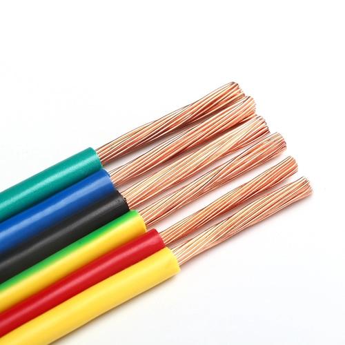
Single Core Power Cable — IEC 60502-1 XLPE/PVC Insulated Single-Core 0.6/1 kV Power Cable with Copper or Aluminum Conductor, Armoured (SWA/STA) or Unarmoured, for Single-Phase Power Distribution, DC Circuits, High-Ampacity Feeders, and Parallel Phase Installations
Power & High Voltage Cables /Single Core Power Series (0.6/1 kV)

Single Core Power Cable — IEC 60502-1 XLPE/PVC Insulated Single-Core 0.6/1 kV Power Cable with Copper or Aluminum Conductor, Armoured (SWA/STA) or Unarmoured, for Single-Phase Power Distribution, DC Circuits, High-Ampacity Feeders, and Parallel Phase Installations

Single core power cable: IEC 60502-1 XLPE or PVC insulated, 0.6/1 kV, copper or aluminum, 1.5–1 000 mm². Armoured SWA/STA or unarmoured. For single-phase circuits, DC power, large feeders >300 mm², parallel phase installations. PE or PVC sheath. Flame retardant IEC 60332. CE, RoHS.

Key Features

IEC 60502-1 compliant single-core construction — the standard 0.6/1 kV power cable in single-conductor format for applications where three separate cables are required, preferred, or where three-core cable is not practical due to size or installation constraints
XLPE (90°C) or PVC (70°C) insulation — XLPE for higher ampacity per cross-section and 130°C overload capability; PVC for cost-sensitive indoor installations where the 70°C rating and 11% larger cross-section (for equivalent ampacity) are acceptable
Copper or aluminum conductor — copper for standard installations 1.5–1 000 mm²; aluminum for weight reduction in large cross-sections ≥16 mm² where the larger conductor diameter and bi-metallic terminations are accounted for in the design
SWA (steel wire armour) or STA (steel tape armour) — mechanical protection for direct burial, underground duct, cable trench, and industrial installations; single-core armoured cables must be installed with non-magnetic armour glands to prevent circulating current heating
No circulating current in the armour (single-core installation advantage) — with proper non-magnetic gland installation and single-point bonding, the armour does not carry induced circulating current, unlike a three-core cable where phase imbalance can drive armour current
Cross-section range 1.5–1 000 mm² — from small 1.5 mm² control power to 1 000 mm² utility feeder; single-core format allows handling and installation of cross-sections that would be impractical in multi-core construction
PE (ST7) or PVC (ST2) outer sheath — PE for outdoor UV exposure and direct burial with enhanced moisture resistance; PVC for general indoor and cable tray installation
Parallel phase installation — three single-core cables laid in trefoil or flat formation replace one three-core cable; preferred for cross-sections above 400–500 mm² where the weight and bending radius of a three-core cable become unmanageable on a construction site

Applications

Single-phase power distribution — single-core cable for line and neutral conductors in 230 V single-phase circuits where separate cables for each conductor are required by the installation method or earthing systemDC power circuits — positive and negative single-core cables for DC distribution in solar PV farms, battery energy storage systems, data center DC power distribution, and railway traction power supplyLarge feeder circuits (>300 mm²) — three single-core cables in trefoil or flat formation for main distribution feeders where a three-core cable would exceed practical handling weight and bending radius limitsSubstation interconnections — single-core cables connecting transformers to switchgear, bus sections to bus sections, and substation equipment interconnections where phase separation is required or preferredIndustrial motor and drive connections — single-core cables from VFD cabinets to large motors where the phase conductors are routed separately for cooling, accessibility, or conduit installationBuilding riser and vertical distribution — single-core cables pulled vertically in building riser shafts for main distribution from ground-floor substation to upper-floor distribution boardsTemporary power supply — construction site and event power distribution where single-core cables with camlock connectors provide flexible, reconfigurable power distribution at 400 A and above

Technical Specifications

Standard IEC 60502-1: Power cables with extruded insulation for rated voltages 0.6/1 kV (Um = 1.2 kV)
Rated Voltage (U₀/U) 0.6/1 kV (Um = 1.2 kV)
Conductor Material — Copper Bare copper or tinned copper; IEC 60228 Class 1 (solid ≤4 mm²), Class 2 (stranded ≥6 mm²); circular or compacted circular
Conductor Material — Aluminum Aluminum (≥99.5%); IEC 60228 Class 2; for cross-sections ≥16 mm²
Conductor Cross-Sections — Copper 1.5, 2.5, 4, 6, 10, 16, 25, 35, 50, 70, 95, 120, 150, 185, 240, 300, 400, 500, 630, 800, 1 000 mm²
Conductor Cross-Sections — Aluminum 16, 25, 35, 50, 70, 95, 120, 150, 185, 240, 300, 400, 500, 630, 800, 1 000 mm²
Conductor Shape Circular stranded (standard); compacted circular (reduced OD) for ≥50 mm²; the compacted conductor reduces the cable OD by 5–10% and reduces the insulation and sheath material requirement
Insulation — XLPE Cross-linked polyethylene; rated 90°C continuous; 250°C short-circuit (5 s); insulation thickness per IEC 60502-1 Table 3
Insulation — PVC PVC type A per IEC 60502-1; rated 70°C continuous; 160°C short-circuit (5 s)
Insulation Thickness — XLPE (Selected Sizes) 0.7 mm (1.5–6 mm²); 0.9 mm (25–35 mm²); 1.0 mm (50 mm²); 1.1 mm (70–95 mm²); 1.2 mm (120–150 mm²); 1.4 mm (185–240 mm²); 1.6 mm (300 mm²); 1.8 mm (400 mm²); 2.0 mm (500 mm²); per IEC 60502-1
Insulation Color / Identification Brown, black, grey (phase identification L1, L2, L3); blue (neutral); green-yellow (PE); solid color insulation per HD 308 S2
Core Screening (Optional) Copper tape or tinned copper wire screen over insulation; for applications requiring a defined earth reference plane or where earth fault current must be carried by a screen rather than a separate earth conductor
Inner Covering / Bedding Extruded PVC ST2 or PE ST7; or lapped binder tape for unarmoured cables; provides a cylindrical surface for armour application
Armour — SWA (Single-Core) Galvanized steel wire armour; wire diameter 1.6–5.0 mm; applied helically; critical note: single-core SWA must be installed with non-magnetic armour glands and the gland plate material must be non-magnetic (brass or aluminum) to prevent eddy-current heating — steel gland plates on single-core SWA cables will overheat due to induced circulating currents
Armour — STA (Single-Core) Galvanized steel tape armour; double tape with controlled overlap; 0.2–0.8 mm tape thickness; same non-magnetic gland requirement as SWA
Armour — AWA (Aluminum Wire Armour, Optional for Single-Core) Aluminum wire armour; preferred over steel for single-core AC applications because aluminum's lower magnetic permeability reduces circulating current losses and heating compared to steel armour
Outer Sheath — PVC ST2 Extruded PVC type ST2; black RAL 9005; UV-stabilized; standard for general purpose indoor, outdoor, and underground installations
Outer Sheath — PE ST7 Extruded PE type ST7; black; enhanced UV and moisture resistance; preferred for direct burial and submarine shore-end applications where water ingress through the sheath over decades of service must be prevented
Outer Sheath — LSZH (Optional) Low smoke zero halogen compound; for tunnels, stations, enclosed building riser shafts per EN 50575 CPR
Sheath Thickness Per IEC 60502-1 Table 7; from 1.4 mm (smallest cable) to 3.4 mm (largest cable)
Maximum DC Conductor Resistance at 20°C — Copper Per IEC 60228 Class 2; 12.1 Ω/km (1.5 mm²) to 0.0176 Ω/km (1 000 mm²)
Maximum DC Conductor Resistance at 20°C — Aluminum Per IEC 60228 Class 2; 1.91 Ω/km (16 mm²) to 0.0291 Ω/km (1 000 mm²)
Insulation Resistance at 20°C — XLPE ≥1 000 MΩ·km (core-to-earth) per IEC 60502-1
Insulation Resistance at 20°C — PVC ≥36.8 MΩ·km (core-to-earth) per IEC 60502-1
Test Voltage 3 500 V AC / 5 min (power frequency withstand, routine test)
Temperature Range (PVC Sheath) -15°C to +70°C (continuous); 0°C minimum during installation
Temperature Range (PE Sheath) -40°C to +80°C (continuous); -20°C minimum during installation
Minimum Bending Radius 15× cable OD (single-core unarmoured); 15× cable OD (single-core armoured); per IEC 60502-1
Maximum Pulling Tension 50 N/mm² of total copper conductor cross-section; 30 N/mm² for aluminum; use cable stocking over sheath, not pulling eye on conductor
Current Rating (Typical, Copper/XLPE, In Air, 30°C) Per IEC 60364-5-52; 1.5 mm² = 24 A; 2.5 mm² = 33 A; 4 mm² = 45 A; 10 mm² = 80 A; 35 mm² = 170 A; 120 mm² = 370 A; 300 mm² = 645 A; 630 mm² = 1 010 A; 1 000 mm² = 1 340 A; de-rate per installation method and grouping
Short-Circuit Temperature — XLPE 250°C (max 5 s)
Short-Circuit Temperature — PVC 160°C (max 5 s)
Flame Retardant — PVC Sheath IEC 60332-1-2 (single cable); IEC 60332-3 (bunched, on request)
Flame Retardant — PE Sheath PE is not inherently flame retardant; for flame-retardant installation, specify PVC or LSZH sheath
Certifications CE, RoHS; BASEC, KEMA KEUR, VDE on request per national market

Detailed Description

What Is a Single Core Power Cable?

A single core power cable is a 0.6/1 kV cable containing one insulated conductor — one phase, one neutral, one earth, or one DC polarity — in a single cable assembly with its own armour and outer sheath. It is not "incomplete" three-core cable; it is a distinct cable type with its own applications, advantages, and installation requirements.

In power distribution, single-core cables are used in three ways:

  1. For single-phase circuits: One line conductor and one neutral conductor, each as a separate single-core cable
  2. For DC circuits: Separate positive and negative single-core cables
  3. For three-phase circuits: Three single-core cables laid in parallel (trefoil or flat formation), replacing one three-core cable
The last case — three single-core cables for a three-phase circuit — is the most common industrial application. Above approximately 300–500 mm², a three-core cable becomes difficult to manufacture, transport, and install due to weight and bending radius. Three single-core cables are individually lighter, more flexible, and can be routed separately for cooling. They are the standard for large feeder circuits in power plants, substations, and heavy industrial installations.

Single-Core vs Three-Core — When Separate Phases Are Better

ConsiderationSingle-Core (3 Cables)Three-Core (1 Cable)
Weight per cableLower — one phase per cableHigher — three phases in one assembly
Handling and pullingEasier — individually manageableDifficult — heavier reel, requires larger team or winch
Bending radiusSmaller individual OD — smaller bend radiusLarger OD — larger bend radius; may require larger cable trench radius
Heat dissipationBetter — each phase has full air circulation around the cableWorse — phases are in mutual thermal contact
Ampacity (same total cross-section)Higher — better coolingLower — mutual heating
Phase balancingEasier — each cable can be routed independently to equalize lengthFixed — all phases follow the same path
Magnetic fieldHigher external magnetic field if phases are separated; canceled if laid in trefoilLower external field — phases are tightly coupled
Armour heating (AC)Critical issue — steel SWA on single-core must use non-magnetic glands; aluminum armour preferredLess critical — phase currents sum to near zero, minimizing net induced current
Installation costHigher — three cable pulls, three terminationsLower — one cable pull, one termination set
Typical cross-section rangeAny size, but preferred ≥185 mm²≤400 mm² standard; up to 630 mm² on request

The Single-Core SWA Problem — Non-Magnetic Glands Are Not Optional

This is one of the most common installation errors in industrial power distribution: installing single-core steel wire armoured (SWA) cable with standard steel cable glands. The problem:

In a single-core AC cable, the current in the conductor induces a magnetic field around the cable. This time-varying magnetic field induces eddy currents in any conductive material surrounding the conductor — including the steel armour wires, the steel gland, and the steel gland plate. The eddy currents generate I²R heating. If the gland and gland plate are magnetic steel, the magnetic permeability concentrates the flux, increasing the eddy current heating. The result: the gland can reach temperatures exceeding 100°C, damaging the cable sheath at the gland entry and potentially causing insulation failure.

The solution has three parts:

  1. Non-magnetic glands: Brass or aluminum cable glands replace standard steel glands. These materials are non-magnetic and have higher resistivity, reducing eddy current magnitude
  2. Non-magnetic gland plates: The gland mounting plate must also be non-magnetic — brass, aluminum, or non-magnetic stainless steel (grade 316). A steel gland plate with brass glands still creates a magnetic circuit through the plate
  3. Aluminum wire armour (AWA) for single-core: Where SWA is traditionally specified, aluminum wire armour is electrically and magnetically superior for single-core AC applications. Aluminum is non-magnetic (relative permeability ≈1) and has lower resistivity than steel, further reducing eddy current losses
For DC single-core cables, magnetic materials are acceptable — the steady-state DC current produces a static magnetic field that does not induce eddy currents in the armour or glands.

Parallel Phase Installation — Ampacity Through Multiplication

When a single 630 mm² conductor cannot carry the required current (e.g., a 2 500 A feeder), parallel conductors are the solution: two or more single-core cables per phase, connected in parallel at both ends. The current divides between the parallel cables in inverse proportion to their impedances.

For successful parallel operation:

  • All parallel cables per phase must have the same conductor material, cross-section, length, and routing. Differences in length create impedance imbalance, causing unequal current sharing — one cable carries more current, approaches its thermal limit, while the other runs cool
  • The cables must be grouped by phase triplet (L1, L2, L3 together in trefoil or flat), not by parallel group (both L1 cables together). Grouping by phase cancels the magnetic field, reducing external field and inductive reactance
  • Cable spacing between parallel groups must be equal to maintain equal impedance per group
Parallel single-core installation is standard practice for circuits above 1 000–1 600 A — the cross-sections are manageable, the cables are individually handleable, and the installation is simpler than a single conductor of equivalent cross-section (which might be 2 000 mm² and weigh over 20 kg per meter).

Why Choose Yichi Single Core Power Cables

  • XLPE or PVC, copper or aluminum, armoured or unarmoured — you choose: We manufacture all standard combinations. The specification is defined by the application requirements — we do not limit the options to simplify our production
  • Full 1.5–1 000 mm² cross-section range: From control power to utility feeder — a single manufacturer for the complete single-core cable specification
  • AWA (aluminum wire armour) available: For single-core AC applications, aluminum wire armour reduces eddy current losses compared to steel armour. Specify AWA for installations where magnetic gland issues are a concern or where the efficiency loss from armour heating must be minimized
  • Application support for parallel installations: Provide the circuit current, voltage, length, and installation method — we calculate the required cross-section, recommend the number of parallel cables per phase, and verify the current sharing and voltage drop per IEC 60287
  • Type test data available: Full test certificates for conductor resistance, insulation resistance, high-voltage withstand, and armour continuity per IEC 60502-1 for every production batch

Product Inquiry

Product: Single Core Power Cable — IEC 60502-1 XLPE/PVC Insulated Single-Core 0.6/1 kV Power Cable with Copper or Aluminum Conductor, Armoured (SWA/STA) or Unarmoured, for Single-Phase Power Distribution, DC Circuits, High-Ampacity Feeders, and Parallel Phase Installations

Add technical specifications (optional)

The more detail you provide, the faster and more accurate our quotation.

No file chosen

PDF, Office, image or CAD file — up to 5 MB

Need Help?

Certifications

ISO 9001
Quality
CE
European
RoHS
Environmental
TÜV
Certification

Need a Quote for This Product?

Send us your requirements and receive a detailed quotation within 24 hours.