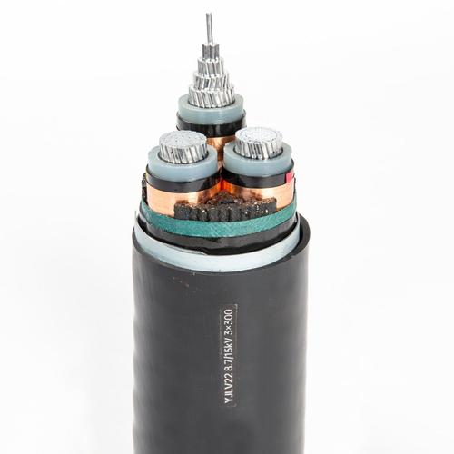
Medium Voltage Power Cable (6–35kV) — IEC 60502-2 XLPE Insulated Single-Core and Three-Core Armoured Power Cable for Primary Distribution Networks, Substation Feeders, and Industrial MV Power Supply
Power & High Voltage Cables /Medium Voltage Power Distribution (6–35 kV)

Medium Voltage Power Cable (6–35kV) — IEC 60502-2 XLPE Insulated Single-Core and Three-Core Armoured Power Cable for Primary Distribution Networks, Substation Feeders, and Industrial MV Power Supply

Medium voltage power cable 6-35kV: IEC 60502-2 XLPE insulated, copper tape/wire screen, SWA/STA armoured. 25–1 000 mm² single-core, 25–630 mm² three-core. Semicon conductor and insulation screens, metallic screen. For primary distribution, substation feeders, industrial MV supply. Partial discharge tested. CE, RoHS.

Key Features

IEC 60502-2 compliant — the international standard for extruded insulation power cables rated 6 kV to 30 kV (Um = 36 kV) covering single-core and three-core construction for fixed MV distribution
XLPE (cross-linked polyethylene) insulation with triple extrusion — conductor screen + XLPE insulation + insulation screen applied in a single continuous triple-extrusion process to eliminate interfacial voids, the primary cause of partial discharge and progressive insulation failure in MV cables
Semiconductive conductor screen — extruded thermoset semicon layer bonded to the conductor eliminates air gaps at the conductor-insulation interface where electric field stress is highest, preventing partial discharge inception at operating voltage
Semiconductive insulation screen — extruded thermoset semicon layer bonded to the XLPE insulation surface; fully bonded and removable for jointing; ensures uniform electric field at the insulation-screen interface
Copper tape or copper wire metallic screen — carries earth fault current back to source, provides a defined zero-potential reference plane, and enables sheath voltage limiter (SVL) protection at bonding points; screen cross-section sized per IEC 60949 earth fault current and duration
Single-core and three-core construction — single-core for high-ampacity feeders and cross-bonded installations; three-core for balanced-circuit installations where phase separation is not required
SWA (steel wire armour) or STA (steel tape armour) — mechanical protection for direct burial, underground duct, and cable bridge installations with impact, crushing, and rodent risk
Partial discharge tested at 1.73 U₀ — ≤5 pC maximum PD level per IEC 60885-3; every production length is PD-tested to verify the integrity of the triple-extruded insulation system

Applications

Primary distribution networks — feeder cables from primary substations (HV/MV transformers) to secondary substations (MV/LV transformers) in utility distribution grids at 6.6 kV, 11 kV, 20 kV, and 33 kVIndustrial medium voltage power supply — MV feeders from the utility point of common coupling (PCC) to the plant main switchgear for factories, refineries, mines, and process plants with MV motor loadsSubstation interconnections — MV bus ties, transformer feeders, and capacitor bank connections within substation switchyardsWind farm collector circuits — 33 kV three-core cables connecting wind turbine generators in series (daisy-chain topology) back to the wind farm substationSolar PV farm MV collection — 20 kV or 33 kV underground cables from inverter stations to the solar farm substation for grid interconnectionUnderground urban distribution — direct-buried or duct-installed MV cables replacing overhead lines in urban and environmentally sensitive areasMining and quarry MV supply — armoured cables for dragline, shovel, and processing plant power supply at 6.6 kV or 11 kV

Technical Specifications

Standard IEC 60502-2: Power cables with extruded insulation and their accessories for rated voltages from 6 kV (Um = 7.2 kV) up to 30 kV (Um = 36 kV)
Rated Voltages Available (U₀/U) 3.6/6 kV (Um = 7.2 kV); 6/10 kV (Um = 12 kV); 8.7/15 kV (Um = 17.5 kV); 12/20 kV (Um = 24 kV); 18/30 kV (Um = 36 kV)
Conductor Material — Copper Bare copper; IEC 60228 Class 2 (stranded) or Class 5 (flexible, on request)
Conductor Material — Aluminum Aluminum (99.5%); IEC 60228 Class 2; for weight reduction in large cross-sections
Conductor Shape Circular stranded (standard); compacted circular or shaped (on request — reduces cable OD and increases ampacity per OD)
Conductor Cross-Sections — Copper 25, 35, 50, 70, 95, 120, 150, 185, 240, 300, 400, 500, 630, 800, 1 000 mm²
Conductor Cross-Sections — Aluminum 25, 35, 50, 70, 95, 120, 150, 185, 240, 300, 400, 500, 630, 800, 1 000 mm²
Conductor Screen Extruded thermoset semiconductive compound; bonded to conductor; minimum thickness 0.3–0.5 mm per IEC 60502-2 Table 6; resistibility per HD 632
Insulation — XLPE Cross-linked polyethylene; rated 90°C continuous; 250°C short-circuit; tree-retardant XLPE (TR-XLPE) available for wet installation conditions where water treeing is a risk
Insulation Thickness — 3.6/6 kV 2.5 mm per IEC 60502-2 Table 8
Insulation Thickness — 6/10 kV 3.4 mm per IEC 60502-2 Table 8
Insulation Thickness — 8.7/15 kV 4.5 mm per IEC 60502-2 Table 8
Insulation Thickness — 12/20 kV 5.5 mm per IEC 60502-2 Table 8
Insulation Thickness — 18/30 kV 8.0 mm per IEC 60502-2 Table 8
Insulation Screen Extruded thermoset semiconductive compound; bonded to insulation; fully bonded and strippable for jointing; minimum thickness 0.3–0.6 mm per IEC 60502-2 Table 7
Insulation Screen Resistibility <500 Ω·m (at 90°C) per IEC 60502-2; ensures the screen can discharge capacitive current without localized heating
Metallic Screen — Copper Tape Helically applied copper tape with controlled overlap (typically 15%); 0.1 mm thickness; effective cross-section for earth fault current sizing
Metallic Screen — Copper Wire Helically applied copper wires over a counter-helix of copper tape; wire diameter 0.7–1.5 mm; higher fault current capacity than tape screen
Metallic Screen Cross-Section (Typical) 16–120 mm² copper equivalent, sized per IEC 60949 for the installation's earth fault level and protection clearing time
Metallic Screen — Aluminum Wire (Optional) For aluminum conductor cables where galvanic compatibility at joints is preferred
Separation Sheath / Bedding Extruded PVC ST2 or PE ST7; provides a cylindrical bedding surface for armouring and an additional moisture barrier
Armour — SWA Galvanized steel wire armour; wire diameter sized per IEC 60502-2 Table 11; applied helically
Armour — STA Galvanized steel tape armour; double tape with controlled overlap; for reduced weight installations where tensile strength is not critical
Outer Sheath — PVC PVC type ST2 per IEC 60502-2; black RAL 9005; UV-stabilized; standard for general-purpose installation
Outer Sheath — PE PE type ST7 per IEC 60502-2; black; enhanced moisture barrier and UV resistance for direct burial and submarine shore-end applications
Outer Sheath — LSZH (Optional) Low smoke zero halogen compound; for tunnels, stations, and enclosed public spaces per EN 50575 CPR
Sheath Thickness Per IEC 60502-2 Table 12; 1.8 mm (20 mm cable sheath OD) to 3.4 mm (80 mm cable sheath OD)
Conductor DC Resistance at 20°C — Copper Per IEC 60228 Table 2; e.g., 0.727 Ω/km (25 mm²) to 0.0176 Ω/km (1 000 mm²)
Conductor DC Resistance at 20°C — Aluminum Per IEC 60228 Table 2; e.g., 1.20 Ω/km (25 mm²) to 0.0291 Ω/km (1 000 mm²)
Insulation Resistance at 20°C — XLPE ≥1 000 MΩ·km at 20°C (core-to-screen at 500 V DC, 1 min); Kᵢ ≥3.67 MΩ·km per IEC 60502-2
Test Voltage (AC) 3.5 U₀ / 5 min (type test); 2.5 U₀ / 5 min (routine test); per IEC 60502-2 Table 14
Partial Discharge (PD) — Routine Test ≤5 pC at 1.73 U₀ per IEC 60885-3; measured after AC voltage withstand test on every production length
Dielectric Power Factor (Tan δ) — Type Test ≤40 × 10⁻⁴ at U₀ and 0.6 U₀; ≤80 × 10⁻⁴ at 2 U₀; per IEC 60502-2; indicates low dielectric losses in the insulation system
Temperature Range — Continuous -20°C to +90°C (conductor temperature; XLPE); sheath surface temperature must not exceed PVC 70°C / PE 80°C / LSZH 70°C
Short-Circuit Temperature — Conductor 250°C (max 5 s) per IEC 60949 for XLPE insulated cables
Short-Circuit Temperature — Metallic Screen 200°C (copper screen, max 5 s) per IEC 60949
Minimum Bending Radius (Installation) 15× cable OD (single-core); 12× cable OD (three-core unarmoured); 15× cable OD (three-core armoured); per IEC 60502-2 Annex B
Maximum Pulling Tension 50 N/mm² of total copper conductor cross-section; 30 N/mm² of aluminum
Flame Retardant IEC 60332-1-2 (single cable); IEC 60332-3-24 Cat C (bunched, on request)
Halogen-Free / LSZH (Optional) IEC 60754-1/2; IEC 61034-2; smoke density ≤60% light transmittance
Certifications CE, RoHS; type test certificates to IEC 60502-2 available; KEMA, VDE, BASEC on request

Detailed Description

What Is a Medium Voltage Power Cable?

A medium voltage (MV) power cable is a power cable rated for continuous phase-to-phase operation between 3.6 kV and 30 kV (Um = 36 kV), defined by IEC 60502-2. MV cables sit between the low voltage distribution network (0.6/1 kV) and the high voltage transmission system (≥66 kV) — they are the feeders that carry power from primary substations to secondary substations, from the utility connection point to the industrial plant, and from the wind turbine generator to the wind farm collector substation.

The critical difference between a low voltage (0.6/1 kV) and a medium voltage cable is the presence of semiconductive screens on both sides of the XLPE insulation — a conductor screen between the conductor and the insulation, and an insulation screen between the insulation and the metallic screen. At MV voltages, the electric field gradient within the insulation is high enough (typically 2–5 kV/mm at operating voltage) that any microscopic void, contamination, or irregularity at the conductor-insulation interface becomes a partial discharge inception point. Partial discharge erodes the insulation progressively — what starts as a 5 pC discharge can grow to cable failure after months or years in service.

The semiconductive screens operate at the conductor and earth potential respectively, creating smooth, void-free equipotential boundaries on both sides of the insulation. The elimination of air gaps at these interfaces is the defining manufacturing requirement for MV cable — achieved through the triple-extrusion process where all three layers (conductor screen, XLPE insulation, insulation screen) are extruded simultaneously in one head and cross-linked together under heat and pressure.

MV Voltage Classes — Which Rating for Your System?

System Voltage (Uₙ)IEC Cable Rating (U₀/U)Um (Max)Typical Application
6.0 kV or 6.6 kV3.6/6 kV or 6/10 kV7.2 kV / 12 kVMining, industrial plants with MV motors
10 kV or 11 kV6/10 kV or 8.7/15 kV12 kV / 17.5 kVCommon utility distribution in Europe and Asia
15 kV or 13.8 kV8.7/15 kV17.5 kVNorth American utility distribution and industrial
20 kV12/20 kV24 kVEuropean medium voltage distribution standard
30 kV or 33 kV18/30 kV36 kVWind farm collector circuits, UK and Commonwealth distribution

The selection rule for U₀ (phase-to-ground rating) is: the cable's U₀ must be equal to or greater than the system's maximum continuous phase-to-ground voltage under all normal and single-earth-fault conditions. For a solidly earthed system, U₀ = Uₙ/√3. For a system that can operate with an earth fault for an extended time (resonant-earthing, isolated neutral), the U₀ may need to equal Uₙ — a significantly higher cable rating, and the reason an 11 kV system with isolated neutral may specify an 8.7/15 kV cable (U₀ = 8.7 kV ≈ 11 kV × 0.8) rather than a 6/10 kV (U₀ = 6 kV ≈ 11 kV/√3).

Single-Core vs Three-Core MV Cable

ParameterSingle-CoreThree-Core
Cable OD per phaseSmaller individual OD — easier handling and bendingLarger OD — heavier per meter, requires larger bending radius
Ampacity (same cross-section)Higher — better heat dissipationLower — mutual heating between phases in one cable
InstallationThree separate cables laid in trefoil or flat formationOne cable with all three phases; simpler routing
Metallic screen bondingCross-bonding required for long runs to minimize circulating current lossesSingle-point or solid bonding — circulating currents balanced within the cable if armoured
Earth fault screen sizingScreen sized per single-core fault current pathScreen sizing can rely on mutual screen coupling
Typical applicationLarge cross-sections (≥300 mm²), long runs, cross-bonded installationsMedium cross-sections, urban distribution, simple installations
Manufacturing lengthLonger possible (smaller reel weight per phase)Shorter (heavier reel); limited by transport weight

Three-core cable is the default for most MV distribution because it is simpler to install and joint — one cable trench, one cable pull, one joint per circuit. Single-core cable is used where the cross-section exceeds what is practical in three-core construction (typically above 400–500 mm²), where the length requires cross-bonding for screen loss management, or where the cable weight of a three-core cable would be unmanageable for installation.

Partial Discharge — The MV Cable Quality Gate

Partial discharge (PD) testing is the definitive quality test for MV cable — it verifies that the triple-extruded insulation system is free of the voids, contaminants, and interface irregularities that cause progressive insulation failure. The test standard is IEC 60885-3.

PD test procedure for every production length:
  1. Voltage is raised smoothly to 2 U₀ and held for 10 seconds
  2. Voltage is reduced to 1.73 U₀
  3. PD magnitude is measured at 1.73 U₀ — must be ≤5 pC
  4. A discharge exceeding 5 pC at 1.73 U₀ is cause for rejection — the cable length is cut, the defect section is removed, and the remaining sections are re-tested
  5. The test is repeated for each core of a multi-core cable
A cable that passes PD at the factory leaving no voids greater than the 5 pC threshold is reliable for its full 30+ year design life. A cable that passes a simple AC withstand test but is not PD-tested can have voids that will initiate PD after a few months of thermal cycling in service — and PD, once started, never self-heals.

Metallic Screen Sizing — Earth Fault Current

The metallic screen (copper tape or copper wires) serves two functions: it provides a defined earth reference plane (capacitive grading), and it carries earth fault current from the fault point back to the source. The second function determines the screen cross-section:

  • Screen cross-section (A) = √(I² × t) / K, where:
- I = earth fault current (kA rms, symmetrical)

- t = fault clearing time (seconds, from protection relay setting)

- K = material constant: 226 for copper (adiabatic, 200°C final); 148 for aluminum

For example: 12 kA earth fault, 0.5 s clearing time → A = √(144 × 0.5) / 226 = √72 / 226 ≈ 37.7 mm² copper equivalent. A 50 mm² copper wire screen would be specified with margin.

Insufficient screen cross-section is a common cause of MV cable failure — the screen melts during an earth fault before the protection relay clears, the fault arc transfers to the armouring or adjacent phases, and a single-phase-to-earth fault escalates to a three-phase fault.

Why Choose Yichi Medium Voltage Power Cables

  • Triple-extruded XLPE insulation system: Conductor screen, XLPE insulation, and insulation screen are extruded simultaneously in a single head on a CCV (catenary continuous vulcanization) line. The triple-extrusion process eliminates interfacial voids — the primary source of partial discharge in MV cables
  • Every production length PD-tested: Not a sample test — every meter of every production length is PD-tested to ≤5 pC at 1.73 U₀ per IEC 60885-3. The test result is printed on the cable reel label and the test certificate
  • Type-tested to IEC 60502-2: Full type-test program including partial discharge, dielectric power factor (tan δ) vs voltage, heat cycle voltage test, impulse voltage withstand (BIL), and mechanical tests on all cable constructions
  • Screen cross-section engineered to your earth fault: Provide your system earth fault level and protection clearing time — we calculate and verify the metallic screen cross-section per IEC 60949 and include the calculation in the cable data sheet
  • Custom voltage ratings and constructions: Standard IEC voltage classes are 3.6/6, 6/10, 8.7/15, 12/20, 18/30 kV. Non-standard intermediate voltages, TR-XLPE insulation for wet conditions, and custom screen configurations are available on request
  • Accessories compatibility: We provide jointing and termination guidance compatible with major MV accessory manufacturers (3M, Raychem/TE, Nexans, Pfisterer, Südkabel) — specify your preferred accessory system and we match the cable dimensions accordingly

Product Inquiry

Product: Medium Voltage Power Cable (6–35kV) — IEC 60502-2 XLPE Insulated Single-Core and Three-Core Armoured Power Cable for Primary Distribution Networks, Substation Feeders, and Industrial MV Power Supply

Add technical specifications (optional)

The more detail you provide, the faster and more accurate our quotation.

No file chosen

PDF, Office, image or CAD file — up to 5 MB

Need Help?

Certifications

ISO 9001
Quality
CE
European
RoHS
Environmental
TÜV
Certification

Need a Quote for This Product?

Send us your requirements and receive a detailed quotation within 24 hours.