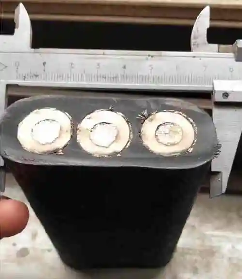
MV Reeling Cable (3.6/6kV–6/10kV) — Medium Voltage Drum-Wound Power Cable with Semiconductive Screens for Large Mining, Crane, and Heavy Industrial Reeling
Reeling & Drum Cables /Medium Voltage MV Series

MV Reeling Cable (3.6/6kV–6/10kV) — Medium Voltage Drum-Wound Power Cable with Semiconductive Screens for Large Mining, Crane, and Heavy Industrial Reeling

Medium voltage reeling cable for 3.6/6 kV to 6/10 kV: EPR insulation with extruded semiconductive conductor and insulation screens, copper tape metallic screen, CR or PUR jacket. IEC 60228 Class 5/6 copper, galvanized steel wire tensile core, 25–400 mm². D/d from 15:1, >100 000 reeling cycles. Partial discharge tested <5 pC at 2 U₀. For large mining draglines, electric rope shovels, STS cranes, tunnel boring machines, and mobile substation reeling at voltages above 1 kV where 0.6/1 kV cable is insufficient.

Key Features

True medium voltage: 3.6/6 kV, 6/10 kV, and 8.7/15 kV — for equipment requiring >1 kV power
Triple-extruded EPR insulation system: conductor screen + EPR insulation + insulation screen in one continuous process
Copper tape metallic screen: provides ground fault current path and uniform electric field distribution
Partial discharge tested <5 pC at 2 U₀ — verified insulation integrity for MV reeling reliability
Galvanized steel wire tensile core — up to 20 kN capacity for deep-drum, long-length MV reeling
CR or PUR jacket — CR for mining standard, PUR for superior abrasion and halogen-free
25–400 mm² power conductors — from 500 kW to 10+ MW equipment
CE, RoHS compliant; MSHA, ATEX, and IEC 60502-2 certified construction

Applications

Large electric mining shovels and draglines — 6.6 kV trailing and reeling cableSTS container cranes — 3.3 kV / 6.6 kV main power reels at major port terminalsTunnel boring machines (TBM) — 6–10 kV continuous advance reelingMobile substation and power distribution — MV reeling for temporary and portable powerBucket wheel excavators and stacker/reclaimers — MV power reels in open-cut miningShip-to-shore power connection — MV reeling for cold-ironing and shore powerLarge dredgers — cutter suction dredger MV power reels

Technical Specifications

Rated Voltage Classes 3.6/6 kV (U₀/U), 6/10 kV, 8.7/15 kV
Conductor Bare copper or tinned copper, IEC 60228 Class 5 (flexible) or Class 6 (extra-flexible)
Conductor Cross-Sections 25–400 mm² (larger on request)
Conductor Screen Extruded semiconductive EPR/XLPE compound — bonded to conductor surface, eliminates air voids
Insulation EPR (ethylene propylene rubber) — medium voltage grade, high dielectric strength
Insulation Thickness Per IEC 60502-2 for rated voltage: 2.5 mm (3.6/6 kV), 3.4 mm (6/10 kV), 4.5 mm (8.7/15 kV)
Insulation Screen Extruded semiconductive compound — strippable for termination, bonded for reliability
Metallic Screen Copper tape (helically applied) or tinned copper braid — individual per core
Metallic Screen Cross-Section ≥16 mm² copper — sized for system ground fault current per IEC 60502-2
Core Identification Color coded or numbered + green-yellow (protective conductor, if required)
Core Assembly 3 cores stranded with anti-torsion fillers; PET fleece between layers
Tensile Reinforcement Galvanized steel wire rope — central core element
Tensile Capacity Up to 20 kN — sized for cable weight and drum depth
Inner Sheath CR or NBR rubber — extruded over core assembly, provides bedding for jacket
Outer Jacket — CR CR (neoprene), Shore 60–70 A; black RAL 9005; heavy-duty
Outer Jacket — PUR PUR (TMPU), Shore 85–90 A; halogen-free; superior abrasion
Jacket Surface Smooth or ribbed — ribbed for wet and marine reeling conditions
Drum Diameter Ratio (D/d) 15:1 (minimum); 20:1 (recommended); 25:1 (extended life)
Reeling Speed Up to 60 m/min
Reeling Life at 20:1 D/d >100 000 cycles (CR); >150 000 cycles (PUR)
Maximum Reel Length Up to 300 m (single-layer equivalent)
Partial Discharge (PD) <5 pC at 2 U₀ — tested per IEC 60885-3
Tan Delta (Dielectric Loss) <40 × 10⁻⁴ at 2 U₀ — verified insulation quality
Test Voltage 11 000–22 000 V AC / 5 min per IEC 60502-2
Temperature Range (CR · Moving) -25°C to +70°C
Temperature Range (PUR · Moving) -40°C to +80°C
Flame Retardant (CR) IEC 60332-1-2; self-extinguishing; MSHA 30 CFR Part 18
Flame Retardant (PUR) IEC 60332-1-2; UL VW-1
Halogen-Free (PUR) IEC 60754-1
Oil Resistance CR: good; PUR: excellent (IEC 60811-404)
UV / Weather Resistance CR: excellent; PUR: excellent (ISO 4892-2)
Certifications CE, RoHS; IEC 60502-2 compliant; MSHA/ATEX on request

Detailed Description

Medium Voltage Cable Construction — Three Critical Layers

At voltages above 1 kV, the electric field stress in the cable insulation becomes the dominant design consideration. A 0.6/1 kV cable has a simple construction: conductor + insulation + jacket. This works because the electric field at 600 V is low enough that minor imperfections in the conductor surface or insulation do not cause problems.

At 6 kV, the electric field is 10× stronger. Microscopic air gaps between the conductor and insulation become sites of partial discharge — tiny electrical arcs that progressively erode the insulation, leading to eventual failure. Three additional layers prevent this:

Layer 1: Conductor Screen (Semiconductive)

An extruded semiconductive compound applied directly over the copper conductor. This layer:

  • Fills the interstitial spaces between individual conductor strands — eliminating air gaps
  • Creates a smooth, uniform electrical surface — no protruding strands that concentrate the electric field
  • Is bonded to the conductor — cannot separate during bending

Layer 2: EPR Insulation (Dielectric)

The primary electrical insulation layer. Thickness per IEC 60502-2:

  • 3.6/6 kV: 2.5 mm
  • 6/10 kV: 3.4 mm
  • 8.7/15 kV: 4.5 mm
EPR is specified (rather than XLPE) for reeling applications because its rubber-like flexibility withstands repeated bending better than the stiffer, semi-crystalline XLPE.

Layer 3: Insulation Screen (Semiconductive)

An extruded semiconductive compound over the EPR insulation. This layer:

  • Provides a smooth outer electrical boundary for the insulation — defines the ground reference surface
  • Is strippable — can be cleanly removed during termination without damaging the EPR insulation
  • Prevents partial discharge between the insulation outer surface and the metallic screen
These three layers are applied in a single triple-extrusion process — all three extruded simultaneously and cross-linked together. This ensures perfect bonding between layers with no contamination or air at the interfaces — the most critical quality requirement for MV cable.

Copper Tape Metallic Screen — Ground Fault and Electric Field Control

Each insulated core has an individual metallic screen — typically helically applied copper tape. The screen serves two functions:

  1. Ground fault current path: In the event of an insulation fault, the screen carries the fault current to ground, enabling the protection system to detect and clear the fault. The screen cross-section (≥16 mm² copper) is sized to carry the system's prospective ground fault current without overheating
  2. Electric field containment: The screen creates a grounded equipotential surface around the insulation. All electric field lines terminate at the screen — no external electric field exists beyond it. This allows the three screened cores to be in direct contact during stranding without risk of phase-to-phase discharge
The copper tape is applied with an overlap (typically 15–20%) to ensure complete coverage during bending. For reeling applications, a tinned copper braid screen may be specified for improved flexibility.

Triple Extrusion — The Manufacturing Difference

The conductor screen, EPR insulation, and insulation screen are extruded in one pass through a triple-head extruder. All three layers exit the die simultaneously and enter a continuous vulcanization (CV) tube where they are cross-linked together.

Why this matters:

  • No contamination between layers: Because all three layers are applied in one continuous process, there is no opportunity for dust, moisture, or handling contamination to enter at the layer interfaces — the most common cause of MV cable failure
  • Molecular-level bonding: The EPR cross-links to the semiconductive screens, creating a seamless transition with no mechanical interface that could separate during bending
  • Uniform thickness: The triple-head die precisely controls all three layer thicknesses — critical because an undersized insulation section at any point creates a weak spot
This is the same manufacturing technology used for utility-grade MV underground power cable — adapted for flexible reeling applications through EPR formulation and stranding design.

Why MV Reeling Requires Conservative D/d Ratios

The minimum bend radius for MV cable (15:1 D/d) is larger than for LV reeling cable (10:1 D/d). Two reasons:

  1. Thicker insulation: MV cable has 2.5–4.5 mm of EPR insulation plus two semiconductive screens. The total insulation system is 3–6 times thicker than LV cable (0.6–1.2 mm PVC/EPR). Thicker layers experience higher bending strain at the inner and outer radii
  2. Triple-extruded layer integrity: The conductor screen-EPR-insulation screen bond must survive millions of bending cycles without delamination. A larger bend radius reduces the shear stress at these bonded interfaces
D/d practical rule: 20:1 for >100 000 cycle life; 25:1 for maximum service life. Do not operate MV reeling cable below 15:1 D/d — partial discharge at the screen interfaces is likely below this threshold.

Why Choose Yichi Cable MV Reeling?

  • Triple-extrusion quality: Our MV cables are manufactured on a triple-head CV extrusion line with in-line diameter and eccentricity monitoring — every millimeter of cable is verified for uniform insulation thickness
  • 100% PD tested: Every meter of MV reeling cable is partial discharge tested at 2 U₀ (<5 pC acceptance) — not batch-sampled. A cable with PD at 2 U₀ will fail in service
  • Tan delta tested: Dielectric loss measurement verifies that the EPR insulation compound is properly cross-linked and free from contaminants — tested on every production length
  • Strippable insulation screen: Our screen compound is formulated for clean, easy stripping during termination — reducing installation time and the risk of insulation damage at the most critical point
  • Application review: Send us your system voltage, prospective fault current, and drum dimensions — we verify conductor size, screen cross-section, and D/d ratio compliance

Frequently Asked Questions

Why does a medium voltage reeling cable need extruded semiconductive screens?

Air voids at the conductor and insulation surfaces are where partial discharge starts and erodes insulation. The conductor screen, EPR insulation, and insulation screen are triple-extruded in one continuous process, which removes those voids at the source.

What partial discharge level is verified, and against which standard?

<5 pC at 2 U₀, tested per IEC 60885-3. Partial discharge testing is the definitive factory check on insulation integrity for MV reeling cable, because it detects defects that a simple voltage withstand test passes.

Which D/d ratio should I specify for a long drum?

15:1 is the minimum, 20:1 is recommended, and 25:1 gives extended life. At 20:1 D/d the reeling life is >100 000 cycles with a CR jacket and >150 000 cycles with PUR. Maximum reel length is approximately 300 m in single-layer equivalent.

How is the cable prevented from stretching on a deep drum?

A central galvanized steel wire rope provides the tensile capacity, up to 20 kN, sized to the cable weight and drum depth. The copper conductors therefore carry no tension during reeling. Cores are available from 25 mm² to 400 mm² at 3.6/6 kV, 6/10 kV, and 8.7/15 kV.

Product Inquiry

Product: MV Reeling Cable (3.6/6kV–6/10kV) — Medium Voltage Drum-Wound Power Cable with Semiconductive Screens for Large Mining, Crane, and Heavy Industrial Reeling

Add technical specifications (optional)

The more detail you provide, the faster and more accurate our quotation.

No file chosen

PDF, Office, image or CAD file — up to 5 MB

Need Help?

Certifications

ISO 9001
Quality
CE
European
RoHS
Environmental
TÜV
Certification

Need a Quote for This Product?

Send us your requirements and receive a detailed quotation within 24 hours.