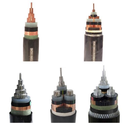
High Voltage Power Cable — IEC 60840 / IEC 62067 XLPE Insulated 66–220 kV Single-Core Power Cable with Metallic Sheath, PE Outer Jacket, and Partial Discharge Guarantee for Transmission Grid, Substation Interconnection, and Long-Distance Underground Power Circuit
Power & High Voltage Cables /High Voltage Transmission (>35 kV)

High Voltage Power Cable — IEC 60840 / IEC 62067 XLPE Insulated 66–220 kV Single-Core Power Cable with Metallic Sheath, PE Outer Jacket, and Partial Discharge Guarantee for Transmission Grid, Substation Interconnection, and Long-Distance Underground Power Circuit

High voltage power cable: IEC 60840 (66–150 kV) and IEC 62067 (220 kV+) XLPE insulated single-core cable. Copper conductor 240–2 500 mm², extruded conductor screen, XLPE insulation with dry-cure CCV, metallic sheath (corrugated aluminum or lead), PE outer jacket. Full PD tested ≤5 pC at 1.5 U₀. For transmission grid, substation interconnection, underground HV circuits.

Key Features

IEC 60840 (Um = 72.5–170 kV) and IEC 62067 (Um > 170 kV) compliant — the international standards for extruded insulation high voltage power cables from 66 kV to 220 kV and above; type-tested for 30+ year design life
XLPE insulation manufactured by dry-cure CCV (catenary continuous vulcanization) with super-clean, super-smooth semiconductive screens — the insulation cleanliness and screen smoothness directly determine the cable's PD inception voltage and long-term electrical treeing resistance
Degassing process controlled to <50 ppm methane in XLPE after cross-linking — residual cross-linking by-products diffuse from the insulation in a heated degassing chamber for 7–30 days depending on insulation thickness; incomplete degassing causes gas pressure build-up under the metallic sheath in service
Corrugated aluminum sheath — helically corrugated seamless aluminum tube applied over the insulation screen cushion layer; provides the radial moisture barrier (essential for preventing water treeing), carries earth fault and short-circuit current, and provides mechanical protection
Extruded semiconductive conductor screen with super-smooth surface finish (asperity ≤50 μm) — any protrusion from the conductor screen into the XLPE insulation creates a local electric field enhancement that can initiate electrical treeing at operating stress of 5–8 kV/mm
Partial discharge tested at 1.5 U₀ — ≤5 pC (IEC 60840) or ≤10 pC (IEC 62067) on every production length; this is the definitive factory quality test that confirms the insulation system is free of critical-size voids and contaminants
Conductor cross-sections from 240 mm² to 2 500 mm² — copper or aluminum; segmented Milliken conductor construction for cross-sections ≥800 mm² to reduce skin effect AC resistance increase at 50/60 Hz
PE (polyethylene) outer jacket with graphite semiconductive outer layer — UV-stabilized for outdoor installation; graphite layer enables sheath voltage testing at the joint to verify jacket integrity after installation

Applications

High voltage transmission circuits — underground and submarine HV cable circuits connecting substations at 66 kV, 110 kV, 132 kV, 150 kV, 220 kV, and with IEC 62067 to 400 kV and 500 kVSubstation interconnections — HV cables between GIS (gas-insulated switchgear) bays, between transformers and GIS, and between substation sections where overhead busbars are impracticalUrban underground HV feeders — replacement of overhead lines in urban and environmentally sensitive areas where overhead transmission is restricted or prohibitedPower plant generator connections — HV cables from the generator step-up transformer to the plant switchyard within power station boundariesOffshore wind farm export cables — 66 kV, 132 kV, or 220 kV submarine cables from offshore substation platforms to onshore grid connection pointsLong-distance underground transmission — extruded XLPE insulated cable circuits up to 20–50 km between substations where overhead line construction is not feasibleInterconnectors and grid reinforcement — HV cable circuits for network reinforcement, load transfer between substations, and interconnection of separate grid areas

Technical Specifications

Standards IEC 60840 (Um = 72.5–170 kV); IEC 62067 (Um > 170 kV up to 550 kV); cable systems type-tested per IEC 60840 / IEC 62067 complete with accessories
Rated Voltages Available (U₀/U) 38/66 kV (Um = 72.5 kV); 50/87 kV (Um = 100 kV); 64/110 kV (Um = 123 kV); 76/132 kV (Um = 145 kV); 87/150 kV (Um = 170 kV); 127/220 kV (Um = 245 kV); 160/275 kV (Um = 300 kV); on request to 290/500 kV
Conductor Material — Copper Bare copper; IEC 60228 Class 2 stranded circular (≤500 mm²); Milliken segmented construction (≥800 mm²) with paper or semiconductive tape separation between segments to reduce skin effect
Conductor Material — Aluminum Aluminum; IEC 60228 Class 2; for weight reduction in very large cross-sections
Conductor Cross-Sections — Copper 240, 300, 400, 500, 630, 800, 1 000, 1 200, 1 400, 1 600, 2 000, 2 500 mm²
Conductor Screen Extruded thermoset super-clean semiconductive compound; minimum thickness 0.8–1.5 mm per IEC 60840 Table 1; super-smooth surface finish (asperity ≤50 μm peak-to-valley); bonded to conductor
XLPE Insulation Extra-clean cross-linked polyethylene compound; peroxide-cured; degassed to <50 ppm methane; rated 90°C continuous, 250°C short-circuit
Insulation Thickness — 38/66 kV 9.0 mm (typical); per IEC 60840 for design electric stress 5–8 kV/mm at U₀
Insulation Thickness — 64/110 kV 13.0–16.0 mm (typical); varies with manufacturer's qualified design
Insulation Thickness — 76/132 kV 15.0–18.0 mm (typical)
Insulation Thickness — 87/150 kV 17.0–21.0 mm (typical)
Insulation Thickness — 127/220 kV 22.0–27.0 mm (typical)
Insulation Screen Extruded thermoset super-clean semiconductive compound; bonded to XLPE insulation; minimum thickness 0.8–1.5 mm; fully bonded and strippable at jointing; super-smooth surface finish
Semi-Conducting Swelling Tape Water-swellable semiconductive tape applied over the insulation screen; ensures longitudinal water blocking in the event of jacket damage and moisture ingress
Metallic Sheath — Corrugated Aluminum Seamless helically corrugated aluminum tube; wall thickness 1.5–2.5 mm; applied continuously on the cable line; provides radial moisture barrier, short-circuit current path, and mechanical protection
Metallic Sheath — Lead (Optional) Extruded lead alloy (0.5 Sb or 2 Sn) sheath; for submarine cables and applications requiring absolute radial water barrier; wall thickness 2.0–4.0 mm
Metallic Sheath Short-Circuit Current Rating Calculated per IEC 60949; typical 20–50 kA / 1 s (aluminum sheath cross-section 250–600 mm²); sized to installation earth fault level
Anti-Corrosion Protection Bitumen compound layer or extruded PE oversheath applied over metallic sheath for buried installation with soil corrosion risk
Outer Jacket — PE PE ST7; black; 3.0–5.0 mm wall thickness; UV-stabilized (carbon black ≥2.5%); graphite semiconductive outer layer for post-installation sheath testing
Outer Jacket — LSZH (Optional) LSZH compound for tunnel and indoor installations per EN 50575 CPR requirements for fire performance in enclosed spaces
Sheath Integrity Test (After Installation) DC voltage test at 10 kV/mm of jacket thickness for 1 minute per IEC 60229; the graphite outer layer enables this test at any point along the installed cable
Maximum Conductor DC Resistance at 20°C — Copper Per IEC 60228; e.g., 0.0754 Ω/km (240 mm²) to 0.00721 Ω/km (2 500 mm²)
Insulation Resistance at 20°C — XLPE ≥1 000 MΩ·km at 20°C at 500 V DC per IEC 60840
Resistivity of Semicon Screens <500 Ω·m at 90°C per IEC 60840
Capacitance per Core 0.15–0.35 μF/km (single-core; higher capacitance at lower voltage due to thinner insulation)
Charging Current per Core at 50 Hz (U₀) 2–15 A/km (voltage and capacitance dependent; determines the required rating of sheath voltage limiters at cross-bonded joints)
Test Voltage (AC — Routine) Per IEC 60840 Annex C; typically 1.7 U₀ at resonant frequency for 30–60 minutes; simultaneously monitored for PD
Test Voltage (Lightning Impulse — Type Test) Per IEC 60840 Table 4; 325 kVp for 38/66 kV; 550 kVp for 64/110 kV; 650 kVp for 76/132 kV; 750 kVp for 87/150 kV; 1 050 kVp for 127/220 kV; positive and negative 10 impulses each
Partial Discharge — Routine Test ≤5 pC at 1.5 U₀ per IEC 60840; measured on every production length after AC voltage test
Partial Discharge — Sensitivity ≤2 pC background noise during PD measurement; the PD detection system must be calibrated before each test
Dielectric Power Factor (Tan δ) — Type Test ≤20 × 10⁻⁴ at U₀ and 0.6 U₀; ≤30 × 10⁻⁴ at 2 U₀; measured at ambient temperature and at 95–100°C conductor temperature; the tan δ increase with temperature indicates thermal stability of the insulation system
Temperature Range — Continuous (Conductor) 90°C (XLPE); 70°C (sheath surface, PE jacket)
Short-Circuit Temperature — Conductor 250°C (max 5 s) per IEC 60949
Short-Circuit Temperature — Metallic Sheath 200°C (aluminum) or 200°C (lead alloy) per IEC 60949
Minimum Bending Radius (After Installation) 20× cable OD (minimum); 25× cable OD (recommended for jointing); the larger bend radius protects the insulation-screen interface from delamination
Maximum Sidewall Pressure During Pulling 500 N/m of bend radius for XLPE cable per IEC 60840; excessive sidewall pressure crushes the insulation and reduces PD inception voltage
Maximum Cable Pulling Force Per IEC 60840 Annex B; pulling force calculated from conductor cross-section × 50 N/mm² (copper) or 30 N/mm² (aluminum)
Flame Retardant — PE Jacket IEC 60332-1-2; PE jackets are not inherently flame retardant — for fire-critical installations, specify LSZH jacket option
Certifications CE, RoHS; type test reports to IEC 60840 / IEC 62067; KEMA, CESI, or DNV type test certification available on request

Detailed Description

What Is a High Voltage Power Cable?

A high voltage (HV) power cable is an extruded XLPE insulated single-core cable rated for continuous operation at phase-to-phase voltages above 35 kV — typically 66 kV, 110 kV, 132 kV, 150 kV, and 220 kV per IEC 60840, and 275 kV, 400 kV, and 500 kV per IEC 62067. These cables are the backbone of underground and submarine power transmission — they carry hundreds of megawatts between substations in circuits that can extend 20–50 km or longer without intermediate joints.

The jump from MV (≤36 kV) to HV (≥66 kV) is not simply a matter of thicker insulation. The electric field stress at operating voltage is higher — typically 5–8 kV/mm at U₀ compared to 2–5 kV/mm for MV — and this stress is sustained for 30–50 years of continuous operation. At these stress levels, every microscopic imperfection in the insulation system becomes a potential failure mechanism. The manufacturing requirements for HV cable are an order of magnitude more stringent than for MV:

  • Cleanliness: The XLPE insulation compound must be handled in a clean-room environment to prevent any particle contamination greater than 50–100 μm — a particle of this size at the conductor-screen interface can cause an electric field enhancement of 2–5× the average stress, sufficient to initiate electrical treeing over the cable's life
  • Smoothness: The semiconductive screens must have a surface finish with asperities (peaks) less than 50 μm — any protrusion from the conductor screen into the insulation creates a local field enhancement
  • Degassing: After cross-linking, the XLPE insulation must be heated in a degassing chamber for 7–30 days to reduce residual cross-linking by-products (primarily methane, cumyl alcohol, and acetophenone) to levels that do not create gas pressure or chemical degradation of the semicon screens over time
  • Partial discharge: The PD acceptance level at the factory is ≤5 pC at 1.5 U₀ — a single void larger than approximately 0.1 mm in the insulation or at the screen interfaces will produce a >5 pC discharge and cause the cable to be rejected

The Triple-Extrusion XLPE Insulation System

The core of an HV cable is the extruded insulation system — three coaxial layers extruded simultaneously in one processing step:

Conductor Screen (Inner Semicon)

  • Extruded super-clean thermoset semiconductive compound
  • Directly bonded to the conductor to eliminate air gaps at the conductor surface
  • Surface finish: maximum asperity ≤50 μm peak-to-valley
  • Function: provides a smooth equipotential boundary at conductor potential, eliminating air-gap partial discharge at the conductor-insulation interface

XLPE Insulation

  • Extra-clean cross-linkable polyethylene compound, peroxide-cured
  • Insulation thickness: 9 mm (66 kV) to 27 mm (220 kV), designed for 5–8 kV/mm electric stress at U₀
  • The radial electric field in single-core cable at radius r from the conductor center is E(r) = U₀ / [r × ln(R/r_c)], where R is the insulation outer radius and r_c is the conductor screen radius. The maximum stress is at the conductor screen surface (smallest r) — this is the most critical location for insulation cleanliness
  • Degassed to <50 ppm methane after cross-linking

Insulation Screen (Outer Semicon)

  • Extruded super-clean thermoset semiconductive compound
  • Bonded to the XLPE insulation; fully bonded but strippable at jointing for field termination
  • Surface finish: smooth and uniform — the interface between the insulation screen and the metallic sheath (with cushion/swelling layer) must not present field-enhancing irregularities
  • Function: provides a smooth equipotential boundary at earth potential; the bonded screen eliminates the air gap that would otherwise exist between the insulation outer surface and the metallic sheath

Metallic Sheath — Radial Moisture Barrier and Fault Current Path

All HV XLPE cables require a continuous metallic sheath. Its two functions are equally critical:

1. Radial moisture barrier

Water is the primary long-term degradation mechanism for XLPE insulation. Water molecules diffuse into the XLPE over time and, in the presence of the electric field, form water trees — micro-voids filled with water that grow from field-enhancing points. Water trees reduce the dielectric strength of the insulation, lowering the PD inception voltage. Eventually, a water tree bridges enough insulation thickness that the remaining sound insulation fails under operating stress.

The metallic sheath — a seamless corrugated aluminum tube or extruded lead sheath — is 100% impermeable to water vapor. With an intact oversheath, water cannot reach the XLPE insulation for the full 30–50 year design life.

2. Earth fault and short-circuit current path

The metallic sheath carries the earth fault current from a cable fault back to the source — the same function as the copper screen in an MV cable. However, at HV, the fault current is larger (10–50 kA) and the cable circuits are longer, requiring correspondingly larger sheath cross-sections. The corrugated aluminum sheath of an HV cable has a cross-section of 250–600 mm² aluminum, capable of carrying 20–50 kA for 1 second.

Sheath Bonding — Managing Induced Voltages

In a single-core HV cable circuit, the AC current in the phase conductor induces a voltage in the metallic sheath. If the sheath is bonded to earth at both ends of the cable section, the induced voltage drives a circulating current in the sheath — this current generates I²R losses (typically 5–15% of the conductor losses for large cross-sections at 50 Hz) and reduces the cable's ampacity by heating the sheath.

Three sheath bonding methods are used:

Bonding MethodPrincipleLossesApplication
Solid bonding (both ends earthed)Sheath earthed at both ends; circulating current flowsHigh — sheath losses can be 5–15% of conductor lossesShort cable sections (<500 m); low-current circuits
Single-point bondingSheath earthed at one end only; no circulating current path; sheath voltage limiter (SVL) at the un-earthed end protects against transient overvoltagesNegligible — no circulating currentMedium-length sections (500–2 000 m)
Cross-bondingThree single-core cables; sheaths are transposed at joint positions so that each sheath in a major section occupies the positions of all three phases; the induced voltages sum to near zero over the major sectionVery low — residual circulating current onlyLong circuits (>2 000 m); the standard method for long HV cable circuits

A cross-bonded installation requires sheath sectionalizing joints — the joint divides the sheath electrically while maintaining the insulation and moisture barrier continuity. The circuit is divided into major sections (typically three minor sections), and every third joint is a cross-bonding joint where the sheaths are transposed.

Installation and Commissioning — Getting HV Cable Right

  • PD test after installation (AC resonant): The completed cable circuit (cable + joints + terminations) is tested with an AC resonant test set at 1.0–1.7 U₀ for 30–60 minutes with simultaneous PD monitoring. The purpose is not to pass a go/no-go withstand test — it is to confirm that the PD level after installation matches the PD level measured at the factory on each drum length. Any increase in PD at a joint or termination location is investigated and corrected before energization
  • Sheath integrity test (DC): After installation and backfill, the outer PE jacket is tested with 10 kV DC per mm of jacket thickness per IEC 60229. The graphite semiconductive outer layer allows the test to be performed by applying voltage between the metallic sheath and an electrode swept along the cable surface. Any jacket damage that would allow water ingress is located and repaired
  • Sheath voltage limiter (SVL) verification: SVLs at single-point and cross-bonded joints must be tested to confirm their residual voltage at the rated discharge current — typically 10 kA, 8/20 μs waveform. SVL failure during a switching or lightning surge exposes the sheath sectionalizing joint to full induced voltage, causing joint insulation failure
  • Cable pulling: Sidewall pressure at bends must not exceed 500 N/m of bend radius. A pulling dynamometer with a maximum pull-force alarm is standard practice. Lubricated cable rollers are positioned every 2–3 m along the cable route

Why Choose Yichi High Voltage Power Cables

  • Dry-cure CCV manufacturing line with in-line degassing: Our CV (continuous vulcanization) line is a fully dry-cure process — no steam, no water contact with the XLPE during cross-linking. The cable passes directly from the CCV tube into a heated degassing chamber where residual methane is reduced to <50 ppm before the metallic sheath is applied. This is the gold standard for HV cable manufacturing
  • Super-clean, super-smooth semiconductive materials: The conductor screen and insulation screen compounds are sourced from qualified suppliers and handled in a positive-pressure clean-room environment from compound delivery through extrusion. Surface finish and cleanliness are verified by optical inspection before the triple-extrusion head
  • Every production length PD-tested at 1.5 U₀ to ≤5 pC: The PD measurement is the factory's quality gate — no cable length ships with a PD level above the acceptance threshold. The PD data for each production length is included in the documentation package
  • Type-tested to IEC 60840 / IEC 62067: Full type test program including lightning impulse, partial discharge vs voltage, tan δ vs voltage and temperature, heat cycle voltage test, and bending test per the relevant IEC standard. Type test reports available for customer review
  • Jointing and termination support: HV cable accessories (joints, terminations, link boxes, SVLs) are as critical as the cable. We design the cable dimensions to be compatible with major HV accessory systems and provide the complete cable geometry data required for accessory selection
  • Application engineering: Send us your circuit parameters — system voltage, rated current, short-circuit level and duration, route length, installation method, and bonding configuration — and our engineering team calculates the required conductor and sheath cross-sections, ampacity ratings, and recommended bonding scheme per IEC 60287 and IEC 60949

Frequently Asked Questions

How is insulation integrity verified on every production length?

Partial discharge testing at 1.5 U₀ to ≤5 pC for IEC 60840 (72.5–170 kV) and ≤10 pC for IEC 62067 (above 170 kV). PD testing is the definitive factory check that the triple-extruded insulation system contains no voids or protrusions.

What is the purpose of the corrugated aluminium sheath?

It is both the radial moisture barrier and the fault current path. The seamless helically corrugated tube is applied continuously over the insulation screen cushion layer, with a short-circuit rating calculated per IEC 60949 — typically 20–50 kA for 1 s at a 250–600 mm² sheath cross-section.

Why must the XLPE insulation be degassed?

Cross-linking leaves methane and other by-products inside the insulation. The cable is degassed to below 50 ppm methane, because residual by-products would otherwise initiate partial discharge under service stress.

What conductor sizes and voltage classes are available?

Copper from 240 mm² to 2 500 mm², with Milliken segmented construction at 800 mm² and above to limit skin effect. Voltage classes are 38/66 kV, 50/87 kV, 64/110 kV, 76/132 kV, 87/150 kV, and 127/220 kV. An aluminium conductor option reduces weight in very large cross-sections.

Product Inquiry

Product: High Voltage Power Cable — IEC 60840 / IEC 62067 XLPE Insulated 66–220 kV Single-Core Power Cable with Metallic Sheath, PE Outer Jacket, and Partial Discharge Guarantee for Transmission Grid, Substation Interconnection, and Long-Distance Underground Power Circuit

Add technical specifications (optional)

The more detail you provide, the faster and more accurate our quotation.

No file chosen

PDF, Office, image or CAD file — up to 5 MB

Need Help?

Certifications

ISO 9001
Quality
CE
European
RoHS
Environmental
TÜV
Certification

Need a Quote for This Product?

Send us your requirements and receive a detailed quotation within 24 hours.