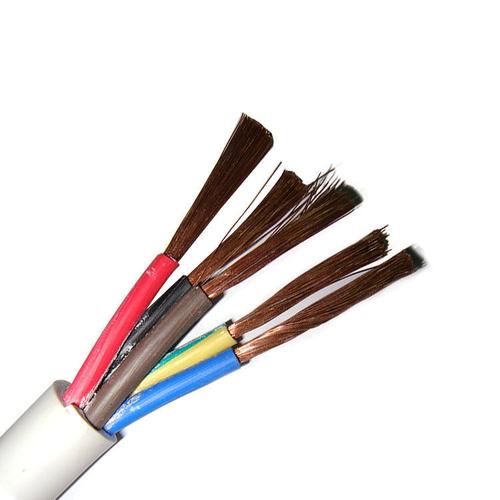
Five-Core Power Cable — IEC 60502-1 XLPE/PVC Insulated 0.6/1 kV 5-Core (3P+N+PE) Power Cable with Copper or Aluminum Conductor, Armoured (SWA/STA) or Unarmoured, for TN-S Three-Phase Distribution, Building Sub-Mains, Motor Circuits, and Industrial Power Supply
Power & High Voltage Cables /Multi-Core Power Series (0.6/1 kV)

Five-Core Power Cable — IEC 60502-1 XLPE/PVC Insulated 0.6/1 kV 5-Core (3P+N+PE) Power Cable with Copper or Aluminum Conductor, Armoured (SWA/STA) or Unarmoured, for TN-S Three-Phase Distribution, Building Sub-Mains, Motor Circuits, and Industrial Power Supply

Five-core power cable: IEC 60502-1 XLPE or PVC insulated, 0.6/1 kV, 5-core (3 phases + neutral + PE), copper or aluminum, 1.5–300 mm². Armoured SWA/STA or unarmoured. For TN-S building distribution, motor circuits, industrial sub-mains. Flame retardant IEC 60332. CE, RoHS.

Key Features

Five-core construction (3P + N + PE) — three phase conductors, one full-size neutral, and one dedicated protective earth conductor in a single cable assembly; designed for TN-S earthing systems where the neutral and earth are separate conductors throughout the installation
IEC 60502-1 compliant — the international standard for low voltage extruded insulation power cables; all five cores are manufactured to the same standard, with the same insulation material and voltage rating
XLPE (90°C) or PVC (70°C) core insulation — XLPE for higher ampacity and 130°C overload capability; PVC for cost-sensitive indoor building installations where the 70°C rating is adequate for the expected load and the PVC cost saving is material to the project
Full-size neutral conductor — the neutral cross-section equals the phase cross-section (3×35 + 2×35 mm², not 3×50 + 25 + 25 mm²) per standard specification; reduced neutral available on request for installations where harmonic currents are negligible and neutral loading is verified to be less than phase loading
SWA (steel wire armour) or STA (steel tape armour) — mechanical protection for direct burial, underground ducts, and industrial environments; the armour also serves as an additional earth fault return path, supplementing the dedicated PE conductor
Copper or aluminum conductor — copper for all standard cross-sections 1.5–300 mm²; aluminum from 16 mm² for weight and cost reduction in larger building distribution feeders where the termination infrastructure (bi-metallic lugs) is specified at design stage
PVC ST2 or PE ST7 outer sheath — PVC for indoor and general purpose outdoor; PE for direct burial and extended outdoor exposure with enhanced UV and moisture resistance
Conductor cross-sections 1.5–300 mm² — from 1.5 mm² lighting and small power distribution to 300 mm² main building feeders serving 400–630 A distribution boards

Applications

TN-S building electrical distribution — five-core cable for three-phase distribution from the main low voltage switchboard to sub-distribution boards in commercial buildings, hospitals, data centers, and industrial facilities where a separate PE conductor is mandatoryThree-phase motor circuits — 5-core cable (3P+N+PE) for motor connections where a neutral is required for the motor control circuit or auxiliary equipment, and a dedicated PE is required for the motor frame earth connectionIndustrial sub-main distribution — armoured five-core cable from the factory main switchboard to machine distribution boards, carrying balanced three-phase power with neutral for single-phase control circuits and a dedicated PE for equipment earthingRenewable energy inverter connections — five-core cable from three-phase solar inverters or battery inverters to the AC distribution board, where the inverter output is three-phase with neutral and the system earthing is TN-SEV charging infrastructure — five-core cable for three-phase EV charger supply circuits in commercial and public charging installations where the charger requires 3-phase + N + PE per IEC 61851Temporary power distribution — heavy-duty five-core rubber or PVC sheathed cable for construction site distribution boards, event power panels, and portable generator connections requiring three-phase with separate neutral and earthBuilding riser and vertical distribution — armoured five-core cable in building riser shafts for vertical power distribution from the ground-floor or basement substation to upper-floor distribution panels

Technical Specifications

Standard IEC 60502-1: Power cables with extruded insulation and their accessories for rated voltages from 1 kV (Um = 1.2 kV) up to 30 kV
Rated Voltage (U₀/U) 0.6/1 kV (Um = 1.2 kV)
Core Configuration 5 cores: 3 phase (L1, L2, L3) + neutral (N) + protective earth (PE); standard cross-section: all 5 cores equal; reduced neutral (e.g., 3×50 + 25 + 25 mm²) available on request
Conductor Material — Copper Bare copper; IEC 60228 Class 1 (solid ≤4 mm²) or Class 2 (stranded ≥6 mm²); circular or compacted circular
Conductor Material — Aluminum Aluminum (99.5%); IEC 60228 Class 2; ≥16 mm²
Conductor Cross-Sections — Copper (All 5 Equal) 1.5, 2.5, 4, 6, 10, 16, 25, 35, 50, 70, 95, 120, 150, 185, 240, 300 mm²
Conductor Cross-Sections — Reduced Neutral (Example) 3×50 + 25 + 25; 3×70 + 35 + 35; 3×95 + 50 + 50; 3×120 + 70 + 70; 3×150 + 70 + 70; 3×185 + 95 + 95; per project specification
Core Insulation — XLPE Cross-linked polyethylene; 90°C continuous; 250°C short-circuit; insulation thickness per IEC 60502-1 Table 3
Core Insulation — PVC PVC type A per IEC 60502-1; 70°C continuous; 160°C short-circuit
Insulation Thickness — XLPE (Selected Sizes) 0.7 mm (1.5–6 mm²); 0.9 mm (25–35 mm²); 1.0 mm (50 mm²); 1.1 mm (70–95 mm²); 1.2 mm (120–150 mm²); 1.4 mm (185–240 mm²); 1.6 mm (300 mm²); per IEC 60502-1
Core Identification — 5-Core (HD 308 S2) Phase L1: brown; Phase L2: black; Phase L3: grey; Neutral (N): blue; Protective Earth (PE): green-yellow; numbered black cores on request
Core Assembly Concentric stranding of insulated cores around a central filler element; the 5-core geometry (pentagonal arrangement) maximizes cable circularity and ensures uniform mechanical stress distribution
Filler Elements Non-hygroscopic PP yarn or rubber compound; fill the interstices between cores to produce a circular inner surface for the bedding or armour layer
Inner Covering / Bedding Extruded PVC ST2 or PE ST7; or lapped binder tape over the core assembly; provides a cylindrical bedding surface for armour wires
Armour — SWA Galvanized steel wire armour; wire diameter per IEC 60502-1 Table 5 (1.25 mm for small cables to 5.0 mm for large cables); helically applied with controlled lay
Armour — STA Galvanized steel tape armour; double tape with ≥25% overlap; tape thickness 0.2–0.8 mm; for installations where tensile strength is less critical
Armour — No Armour (Unarmoured) For cable tray, ladder rack, and above-ground indoor installations where mechanical protection is provided by the cable management system
Outer Sheath — PVC ST2 Extruded PVC type ST2; black; UV-stabilized; standard for general purpose
Outer Sheath — PE ST7 Extruded PE type ST7; black; enhanced UV and moisture resistance for direct burial
Outer Sheath — LSZH (Optional) Low smoke zero halogen compound per EN 50575 CPR; for public buildings, tunnels, and enclosed spaces where smoke and halogen emissions are regulated
Sheath Thickness Per IEC 60502-1 Table 7; calculated from the calculated diameter over the armour or bedding layer
Maximum DC Conductor Resistance at 20°C — Copper Per IEC 60228 Class 2; 12.1 Ω/km (1.5 mm²) to 0.0601 Ω/km (300 mm²)
Maximum DC Conductor Resistance at 20°C — Aluminum Per IEC 60228 Class 2; 1.91 Ω/km (16 mm²) to 0.100 Ω/km (300 mm²)
Insulation Resistance at 20°C — XLPE ≥1 000 MΩ·km (core-to-core and core-to-earth); per IEC 60502-1
Insulation Resistance at 20°C — PVC ≥36.8 MΩ·km (core-to-core and core-to-earth); per IEC 60502-1
Test Voltage (AC) 3 500 V AC / 5 min (routine test, all cores to all other cores and armour)
Temperature Range (PVC Sheath) -15°C to +70°C (continuous); 0°C minimum during installation
Temperature Range (PE Sheath) -40°C to +80°C (continuous); -20°C minimum during installation
Minimum Bending Radius 12× cable OD (unarmoured); 15× cable OD (armoured); per IEC 60502-1
Maximum Pulling Tension 50 N/mm² of total copper conductor cross-section (all 5 cores); 30 N/mm² for aluminum; use cable stocking on outer sheath
Current Rating (Typical, Copper/XLPE, Air, 30°C, Armoured) Per IEC 60364-5-52; 1.5 mm² ≈ 18 A; 2.5 mm² ≈ 25 A; 4 mm² ≈ 34 A; 10 mm² ≈ 62 A; 25 mm² ≈ 107 A; 50 mm² ≈ 162 A; 95 mm² ≈ 243 A; 150 mm² ≈ 325 A; 240 mm² ≈ 442 A; 300 mm² ≈ 504 A; de-rate per installation method and ambient temperature
Short-Circuit Temperature — XLPE 250°C (max 5 s) per IEC 60949
Short-Circuit Temperature — PVC 160°C (max 5 s) per IEC 60949
Flame Retardant IEC 60332-1-2 (single cable); IEC 60332-3 (bunched, on request)
Certifications CE, RoHS; BASEC, KEMA KEUR, VDE on request per national market

Detailed Description

What Is a Five-Core Power Cable?

A five-core power cable is an IEC 60502-1 0.6/1 kV multi-core cable containing five separately insulated conductors in a single assembly: three phase conductors (L1, L2, L3), one neutral conductor (N), and one dedicated protective earth conductor (PE). It is the cable of choice for TN-S (Terre Neutre-Separate) earthing systems — the most common earthing arrangement in modern building electrical installations — where the neutral and protective earth are separate conductors from the supply transformer to the final circuit.

In a TN-S system, the neutral carries the unbalanced return current from single-phase loads, and the PE conductor carries earth fault current from equipment to earth and provides the earth reference for protective devices (RCDs, MCBs) to operate. Keeping these conductors separate ensures that the neutral current does not raise the potential of earthed metalwork, and that a broken neutral does not create a dangerous voltage on equipment enclosures connected to the same conductor.

The five-core cable consolidates all five conductors into one cable pull: one trench, one gland, one termination set at each end. Compare this with the alternative: three single-core phase cables, one single-core neutral, and one single-core PE — five separate cables to pull, gland, and terminate.

Why Five Cores? — The TN-S Earthing System

Earthing SystemNeutral & EarthCable RequiredTypical Application
TN-SSeparate neutral and PE conductors from transformer to load5-core (3P+N+PE) or 5 single-coreModern commercial buildings, hospitals, data centers — the standard for new construction in most countries
TN-C-S (PME)Combined neutral and earth (PEN) from transformer to building entry; separated inside the building4-core (3P+PEN) to building entry; 5-core from building entry onwardUK distribution networks; the PEN is separated at the service head
TTEarth electrode at the installation; neutral earthed at transformer4-core (3P+N) if earth is local rod; or 5-core if a distributed earth is also runRural installations, small buildings with local earth rods
ITNo direct earth connection; earth fault monitored4-core (3P+N) or 5-core depending on designHospitals (operating theatres), mines, ships — where continuity of supply during first earth fault is critical

The five-core cable is mandatory in TN-S installations where the circuit must carry both neutral and PE as separate conductors. It is also used in TN-C-S installations from the point where the PEN is separated (the building main earthing terminal) onward — all sub-main and final distribution circuits after the separation point use five-core cable.

Full-Size vs Reduced Neutral — The Harmonics Question

In traditional 50/60 Hz sinusoidal three-phase systems with balanced linear loads, the neutral current is the vector sum of the three phase currents, which is zero when the phases are perfectly balanced. The neutral was historically specified at half the phase cross-section, and some older installations used 3-core or 3.5-core (reduced neutral) cable.

Modern electrical loads change this calculation:

  • Switch-mode power supplies (computers, LED lighting, electronic ballasts) draw non-sinusoidal current with high third-harmonic content
  • Third-harmonic currents in the three phases are in phase with each other — they add arithmetically in the neutral rather than canceling. A perfectly balanced three-phase load with 33% third-harmonic content produces a neutral current equal to the phase current
  • LED lighting in commercial buildings can produce neutral currents exceeding 100% of the phase current in worst-case scenarios
For this reason, IEC 60364-5-52 now recommends that the neutral conductor in circuits supplying discharge lighting or IT equipment should have a cross-section not less than the phase conductors — the neutral should be 100% (full-size), not 50% (reduced). Yichi five-core cables are manufactured with full-size neutral as standard; reduced neutral is available on request when the load profile is verified to have low harmonic content and the neutral current is calculated to be less than the phase current.

5-Core Cable Identification — Getting the Colors Right

CoreFunctionColor (HD 308 S2)Terminal Designation
1Phase L1BrownL1
2Phase L2BlackL2
3Phase L3GreyL3
4Neutral (N)BlueN
5Protective Earth (PE)Green-YellowPE / ⏚

The green-yellow PE conductor is reserved exclusively for earthing. It must not be used as a phase or neutral conductor under any circumstances, and it must not be over-sleeved to change its identification — the green-yellow color must be integral to the insulation for its entire length. This is a fundamental safety rule in all national wiring regulations based on IEC 60364.

Why Choose Yichi Five-Core Power Cables

  • Full-size neutral as standard — harmonics-ready: All five cores are equal cross-section as standard. If your building has LED lighting, IT equipment, or variable speed drives, the neutral is sized for the harmonic currents that modern loads produce
  • IEC 60502-1 tested and certified: Type-tested construction with full routine testing on every production length — conductor resistance (all 5 cores), insulation resistance (core-to-core and core-to-earth), and AC high-voltage withstand
  • Armoured (SWA/STA) and unarmoured options: Specify SWA for direct burial and underground ducts — the armour provides mechanical protection and serves as a supplementary earth fault path. Specify unarmoured for cable tray and above-ground indoor installation where the mechanical protection is provided by the installation method
  • Copper and aluminum in the full 1.5–300 mm² range: Standard copper for all sizes; aluminum from 16 mm² for weight reduction in large building feeders — one 185 mm² 5-core aluminum cable weighs approximately 40% less than the equivalent copper cable
  • Application support: Provide the building earthing system type (TN-S, TN-C-S, TT), the load profile (linear, non-linear, motor, IT), and the installation method — we recommend the conductor material, cross-section, armour type, and verify the neutral sizing against the harmonic profile

Product Inquiry

Product: Five-Core Power Cable — IEC 60502-1 XLPE/PVC Insulated 0.6/1 kV 5-Core (3P+N+PE) Power Cable with Copper or Aluminum Conductor, Armoured (SWA/STA) or Unarmoured, for TN-S Three-Phase Distribution, Building Sub-Mains, Motor Circuits, and Industrial Power Supply

Add technical specifications (optional)

The more detail you provide, the faster and more accurate our quotation.

No file chosen

PDF, Office, image or CAD file — up to 5 MB

Need Help?

Certifications

ISO 9001
Quality
CE
European
RoHS
Environmental
TÜV
Certification

Need a Quote for This Product?

Send us your requirements and receive a detailed quotation within 24 hours.