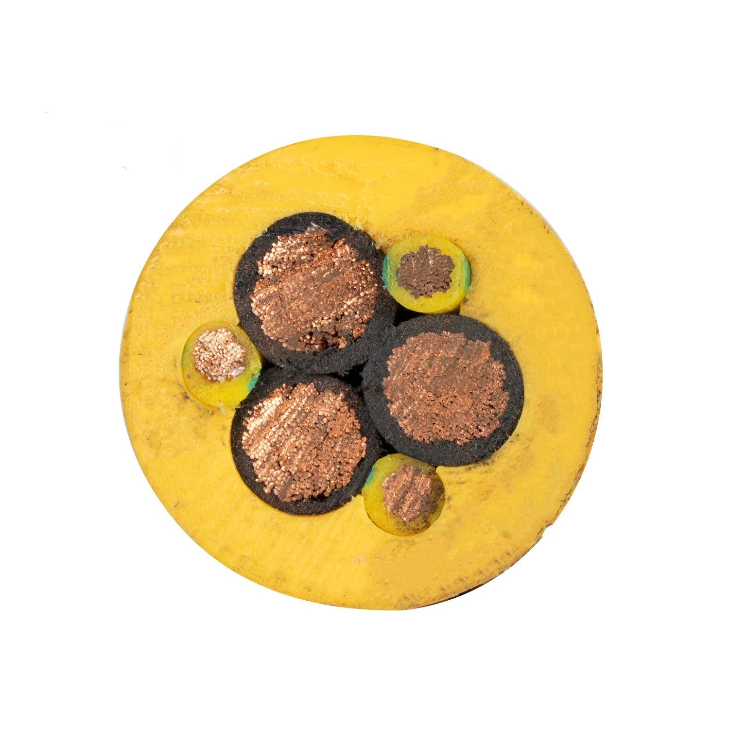
Coal Cutter Composite Specialty Cable — Multi-Core EPR Insulated CR Sheathed Flexible Composite Trailing Cable with Integrated Power, Control, Signal, and Communication Elements for Underground Coal Mining Coal Cutter and Longwall Shearer Machines per AS/NZS 1802 / GB/T 12972
Industrial, Mining & Control Cables /Mining Composite Cable

Coal Cutter Composite Specialty Cable — Multi-Core EPR Insulated CR Sheathed Flexible Composite Trailing Cable with Integrated Power, Control, Signal, and Communication Elements for Underground Coal Mining Coal Cutter and Longwall Shearer Machines per AS/NZS 1802 / GB/T 12972

Coal cutter composite specialty cable: EPR insulated, CR sheathed, 0.6/1 kV to 3.6/6 kV. Integrated power + control + signal + pilot + fiber optic/communication. Class 5 tinned copper. For underground coal mining coal cutters, longwall shearers. Flame retardant, oil/water resistant. AS/NZS 1802, GB/T 12972.

Key Features

Composite construction integrating power cores (0.6/1 kV to 3.6/6 kV), control cores (300/500 V), signal pairs, pilot conductors, and optional fiber optic elements in a single trailing cable — one cable replaces the 3–4 separate cables that would otherwise be required to serve all the electrical functions of a modern coal cutter or longwall shearer
EPR (ethylene propylene rubber) insulation on all cores — the standard mining cable insulation providing the combination of dielectric strength, flexibility, compression recovery, and tear resistance that underground coal trailing cable service demands; EPR is specified for every core regardless of voltage because PVC and XLPE cannot survive the mechanical conditions of trailing cable service
CR (polychloroprene/neoprene) heavy-duty outer sheath — 4.0–8.0 mm wall thickness; the thick rubber sheath protects the internal composite core assembly from the extreme mechanical abuse of the underground mine: dragging across sharp coal and rock, being run over by the machine, struck by falling coal, and continuously abraded against the mine floor
Integrated pilot and ground check conductors for the machine's electrical safety system — the pilot core enables remote control and monitoring from the power centre; the ground check conductor is part of the ground continuity monitoring (GCM) circuit that verifies the machine frame earth is intact before the circuit breaker can close — a mandatory mining safety function
Shielded control and signal pairs — individual aluminum/polyester foil + tinned copper drain wire shielding on the control and signal pairs protects the low-voltage control and communication signals from the electromagnetic interference generated by the high-power cutting motors and the variable speed drive power electronics on the machine
Optional fiber optic elements for machine condition monitoring and automation data — single-mode or multi-mode fibers in a gel-filled stainless steel loose tube, integrated into the core assembly; the fibers carry vibration, temperature, and cutting load data from the machine sensors to the surface control room for real-time coal face monitoring and automation
Flame retardant to AS/NZS 2802 / MSHA — the CR sheath and the complete cable construction pass the mining flame propagation test; a trailing cable fire in the confined underground mine roadway would rapidly consume oxygen and fill the roadway with toxic smoke; the cable's flame-retardant construction is a life-safety requirement
Tinned copper conductors throughout — IEC 60228 Class 5 flexible stranded for all power, control, signal, and pilot cores; tinning prevents copper corrosion in the acidic mine water environment (pH 3–5 from pyrite oxidation) and maintains stable conductor resistance and terminal contact resistance

Applications

Underground coal cutter machine — composite trailing cable supplying all electrical functions to the coal cutter: cutting motor power, hydraulic pump motor power, machine control, sensor feedback, and communication with the surface automation systemLongwall shearer — the most demanding mining composite cable application; the shearer travels back and forth along the longwall face, and the cable is managed by a Bretby cable handler that coils and uncoils the cable as the machine moves; the composite cable integrates all power, control, signal, and fiber optic elements required for the automated longwall operationContinuous miner with automation — composite cable for continuous miners equipped with machine guidance, horizon control, and gas monitoring sensors that require additional signal and data communication conductors beyond the standard Type 441 power + pilot configurationRoadheader and tunnel boring machine — composite cable for roadheaders in underground mine development and TBMs in civil tunnel construction where the machine requires power, control, sensor feedback, and communication in a single trailing cableMine conveyor and material handling — composite cable for long-distance underground conveyor systems where distributed I/O, belt rip detection, bearing temperature monitoring, and CCTV camera power and data are all carried in one cable along the conveyor routeMine ventilation and pumping control — composite cable for the remote control and monitoring of ventilation fans, water pumps, and auxiliary equipment distributed along the mine roadway network

Technical Specifications

Standard — Australia/New Zealand AS/NZS 1802 (Electric cables — reeling and trailing for mining); AS/NZS 2802 (Underground coal mining cables); the composite cable must meet the Type 241 + additional core requirements per the specific mining machine manufacturer's specification
Standard — China GB/T 12972 (Flexible rubber-sheathed cables for mining purposes); covers the coal cutter composite cable types with the full range of core configurations including screened control and communication pairs
Standard — International IEC 60245-4 (applicable test methods for EPR/CR mining cable construction); BS 6708 (flexible cables for mines, UK)
Rated Voltage — Power Cores 0.6/1 kV (standard coal cutter); 1.1/1.1 kV to 3.6/6 kV (longwall shearer and large continuous miner)
Rated Voltage — Control Cores 300/500 V
Rated Voltage — Signal/Data Pairs 300/300 V
Conductor Material Tinned copper; IEC 60228 Class 5 flexible stranded for all core types; tinning is mandatory for the wet, acidic mine water environment — bare copper oxidizes rapidly under these conditions
Power Cores — Cross-Sections 16, 25, 35, 50, 70, 95, 120, 150 mm²; typically 3 power cores (3-phase cutting and hydraulic motors) or 4 power cores depending on the machine's motor configuration
Power Cores — Insulation EPR; rated 90°C; insulation thickness per the voltage class per GB/T 12972 or AS/NZS 1802
Control Cores — Cross-Sections 1.5, 2.5, 4, 6 mm²; 4–24 control cores depending on the machine's control functions; numbered black cores per VDE 0293
Signal Pairs — Construction Twisted pair, 0.75–1.5 mm²; individually shielded with aluminum/polyester foil + tinned copper drain wire; for sensor signals (temperature, pressure, position, vibration) and low-level communication
Signal Pairs — Shielding Foil per pair (100% coverage) + overall braid or foil shield over all signal pairs; the dual-layer shielding ensures signal integrity in the high-EMI environment near the cutting motor VFDs
Pilot Conductor 2.5–6 mm²; insulated and generally unscreened; the pilot core enables the control circuit between the machine and the power centre — typically a 24 V DC or 110 V AC control circuit
Ground Check Conductor 1.5–6 mm²; part of the GCM (ground continuity monitoring) circuit; a pilot signal is sent from the power centre through the ground check conductor to the machine frame and back through the earth conductors — if the earth path is broken, the pilot signal is interrupted and the breaker trips
Earth Conductors Typically 3 earth cores, each cross-section proportioned to the power core cross-section per the cable standard; the 3 earth cores are positioned symmetrically (120° apart) for uniform mechanical and electrical balance
Fiber Optic Elements (Optional) Single-mode (G.652D, 9/125 μm) or multi-mode (OM3/OM4, 50/125 μm); 4–12 fibers in a gel-filled stainless steel loose tube; the tube is integrated into the core assembly in a position that minimizes the bending and compression stress on the fibers during trailing and reeling
Fiber Performance Insertion loss <0.35 dB/km at 1 310 nm (SM); <2.5 dB/km at 850 nm (MM); attenuation change <0.1 dB after simulated trailing cable cycling per the cable manufacturer's fiber test specification
Core Assembly Concentric stranding of all power, control, signal, pilot, and (if included) fiber elements; the radial position of each element type is determined by its mechanical stress sensitivity — earth conductors in the outer layers for maximum mechanical protection, signal pairs in the middle layers for controlled bend radius, power cores distributed for balanced electrical and mechanical loading
Anti-Torsion Fillers EPR or CR rubber filler elements in the interstices between cores; the fillers provide torsional recovery (returning the cable to its neutral lay after twisting), maintain cable circularity, and prevent the cores from shifting position during flexing and trailing
Binder Tape High-temperature polyester or fabric tape wrap over the core assembly; provides mechanical stability during inner sheath extrusion
Inner Sheath — CR Extruded neoprene rubber; 1.5–3.0 mm; provides mechanical protection, electrical insulation between the core assembly and the outer tensile reinforcement, and a bedding layer for the reinforcement
Tensile Reinforcement (Optional) Aramid fibre (Kevlar) or galvanized steel wire braid; applied between the inner and outer sheaths; carries the cable's tensile load during trailing — the copper conductors carry zero tension
Outer Sheath — CR (Standard) Polychloroprene rubber (neoprene); Shore A 60–70; black or orange; 4.0–8.0 mm wall; the sheath is the primary mechanical defence of the cable — the thickness is designed for the mining trailing environment, not for minimum material usage
Outer Sheath — CPE (Cold-Climate) Chlorinated polyethylene; Shore A 60–70; for mines in cold climates where CR stiffens below -25°C; CPE retains flexibility to -40°C
Maximum DC Conductor Resistance at 20°C Per IEC 60228 Class 5 for the conductor cross-section
Insulation Resistance at 20°C — EPR ≥1 000 MΩ·km (core-to-core and core-to-earth at 500 V DC, 1 min)
Test Voltage (AC) — Power Cores, 0.6/1 kV 3 500 V AC / 5 min
Test Voltage (AC) — Power Cores, 3.6/6 kV Per IEC 60502-2; typically 2.5 U₀ / 5 min
Test Voltage (AC) — Control/Signal 2 000 V AC / 5 min (300/500 V rated)
Temperature — Continuous (Conductor) 90°C (EPR)
Temperature — Moving / Flexing (Sheath) -25°C to +60°C (CR); -40°C to +60°C (CPE)
Minimum Bend Radius — Moving (Trailing) 8× cable OD
Flame Retardant Per AS/NZS 2802 / GB/T 12972 / MSHA flame propagation test; the CR sheath and complete cable assembly pass the mining flame test
Oil / Water / Abrasion Resistance Excellent; the CR sheath is formulated for the mine environment — hydraulic oil, mine water (acidic), and severe abrasion against coal and rock
Certifications CE; RoHS; AS/NZS 1802/2802 type testing on request; GB/T 12972 CCC on request; MSHA on request; ISO 9001 manufactured

Detailed Description

What Is Coal Cutter Composite Specialty Cable?

A coal cutter composite specialty cable is a multi-function trailing cable that integrates power conductors, control cores, signal pairs, pilot conductors, and optionally fiber optic communication elements into a single flexible cable assembly for underground coal mining coal cutter and longwall shearer machines. It is the most electrically and mechanically complex cable in underground mining — one cable that carries the cutting motor's power (hundreds of kilowatts at 1 000 V or 3 300 V), the machine control signals (24 V DC), the sensor feedback signals (mV-level vibration and temperature), the pilot circuit for the power centre's protection relay, and the fiber optic data link for the machine's automation and condition monitoring system.

The composite cable's defining engineering challenge is coexistence: all these electrical functions share the same cable core assembly, subjected to the same mechanical abuse — dragged across the mine floor, coiled and uncoiled by the cable handler, run over by the machine, struck by falling coal. The power conductors must deliver motor current without overheating inside the thick sheath. The signal pairs must maintain clean sensor signals despite being bundled alongside high-power conductors carrying inverter switching noise. The optical fibers must survive the same bending and compression that the copper conductors experience without attenuation increase. The design of a composite mining cable is the simultaneous optimization of all these constraints.

Composite Cable vs Standard Mining Cable — Why Integration?

ParameterStandard Mining Cable (Type 241)Composite Mining Cable
Cables per machine3–4 separate: power, control, signal, fiber1 composite cable
Cable handler systems3–4 separate handlers on the machine1 handler — simplified machine design, reduced weight
Cable managementMultiple cables can tangle, twist together, and snag on roof supportsSingle cable is simpler to manage and less likely to tangle
Installation / replacement3–4 cables to pull, terminate, and test1 cable — less downtime during replacement
Core assembly complexitySimple — one function per cableComplex — requires controlled radial positioning of each element type for balanced mechanical and electrical performance
Cost per functionLower per cable, but 3–4× the cable countHigher per cable, but only one cable to purchase, install, and maintain
Typical userOlder machines with separate function cablesModern automated machines with integrated control, monitoring, and communication

The trend in mining machine design is strongly toward the composite cable. Modern longwall shearers and automated continuous miners require the integrated functionality that a composite cable provides. The single-cable solution reduces the machine's cable handler weight (a significant factor on a longwall face where every kilogram of cable handler must be moved back and forth with the shearer), simplifies the cable management in the confined mine roadway, and reduces the number of individual cables that must be replaced when the trailing cable reaches its service life.

Why Choose Yichi Coal Cutter Composite Specialty Cables

  • Engineered core assembly — every element type in its optimal radial position: The power cores, control cores, signal pairs, pilot conductors, earth conductors, and fiber optic elements are not arbitrarily bundled — the radial position of each element type is determined by its mechanical stress sensitivity, thermal performance requirements, and electrical shielding requirements. The core assembly is a designed mechanical and electrical system, not a bundle
  • EPR insulation on all cores — the correct material for mining trailing cable: EPR is specified for every core regardless of voltage or function. We do not substitute PVC or XLPE for the lower-voltage control and signal cores to save cost — PVC would fail from compression and oil exposure, and XLPE would fail from the torsion and flexing that a mining trailing cable experiences. All cores are EPR insulated because all cores experience the same mechanical environment
  • Shielded signal pairs — foil + braid for the mining EMI environment: The cutting motors are driven by variable speed drives (VSDs) that generate high-frequency EMI from the IGBT switching (2–16 kHz with harmonics to tens of MHz). The signal pairs in a composite mining cable must be shielded from this EMI to maintain clean sensor signals — individual foil shields per pair plus an overall braid shield over all signal pairs. The shield transfer impedance is verified at the EMI frequency range of the machine's VSDs
  • Fiber optic integration — validated fiber performance under trailing cable conditions: The fiber loose tube is positioned in the core assembly where the bending and compression stress on the fiber is minimized during trailing and reeling. Fiber attenuation is measured before and after simulated trailing cable cycling — the insertion loss change must be <0.1 dB to ensure the optical data link remains stable throughout the cable's service life
  • Manufactured to the mining machine manufacturer's specification: Coal cutter and longwall shearer composite cables are specified by the machine OEM — the core configuration, voltage class, shield requirements, and fiber count are defined by the machine's electrical design. Yichi manufactures to the OEM cable specification with the same qualified EPR/CR materials and the same quality system as the standard mining cable types

Frequently Asked Questions

What does composite mean in this cable?

Power cores (0.6/1 kV to 3.6/6 kV), control cores (300/500 V), shielded signal pairs (300/300 V), pilot conductors, and optionally fiber optic elements are combined in one trailing cable, so the machine is supplied and controlled through a single cable.

Why use a composite cable rather than several separate trailing cables?

One cable means one trailing or reeling path, fewer terminations, and less weight and congestion on a machine that moves continuously. It also removes the risk of incorrect cable pairing when the machine is reassembled at a new face.

How are the control and signal pairs protected from the power cores?

Signal pairs are individually shielded with aluminium/polyester foil plus a tinned copper drain wire, with a further overall braid or foil shield over the signal group, and the pairs are laid in separate layers from the power cores. Signal pairs are 0.75–1.5 mm² twisted pairs.

What standards and voltage classes apply?

AS/NZS 1802 and AS/NZS 2802, GB/T 12972, and IEC 60245-4 test methods, with flame retardance to AS/NZS 2802 and MSHA. Power cores are 16–150 mm² Class 5 tinned copper at 0.6/1 kV for coal cutters, and 1.1/1.1 kV to 3.6/6 kV for longwall shearers and large continuous miners.

Product Inquiry

Product: Coal Cutter Composite Specialty Cable — Multi-Core EPR Insulated CR Sheathed Flexible Composite Trailing Cable with Integrated Power, Control, Signal, and Communication Elements for Underground Coal Mining Coal Cutter and Longwall Shearer Machines per AS/NZS 1802 / GB/T 12972

Add technical specifications (optional)

The more detail you provide, the faster and more accurate our quotation.

No file chosen

PDF, Office, image or CAD file — up to 5 MB

Need Help?

Certifications

ISO 9001
Quality
CE
European
RoHS
Environmental
TÜV
Certification

Need a Quote for This Product?

Send us your requirements and receive a detailed quotation within 24 hours.