Detailed Description
What Is a Combined Multi-Signal Cable?
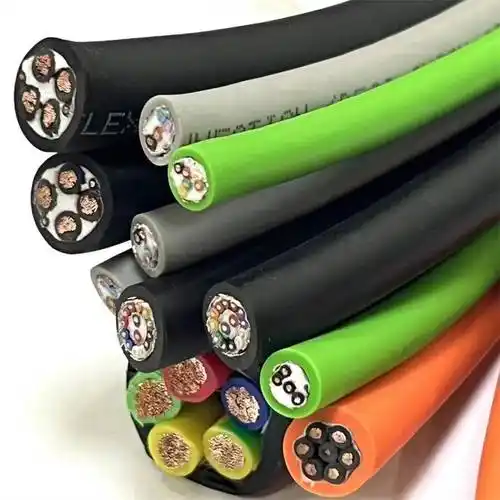
A combined multi-signal cable integrates different types of signal conductors — twisted pairs, coaxial cores, and optionally power conductors — into a single sheathed assembly. This is not simply a multi-pair cable (all pairs the same type) nor a composite power+signal cable (power dominates the design). A combined multi-signal cable is engineered for applications where multiple signal protocols, impedance requirements, and bandwidths must coexist in one physical cable.
Think of it as a custom-designed cable that mirrors your system's wiring diagram:
- Twisted pair #1 and #2: RS-485 differential data (100 Ω, 0.25 mm², individually foil-shielded) — for MODBUS communication between the test rack and the device under test
- Coaxial #1: 50 Ω RF signal path (0.34 mm² inner, PE dielectric, braid outer) — for an RF power measurement or high-speed trigger signal
- Twisted pair #3 and #4: Analog measurement pairs (0.22 mm², PE-insulated, individually foil-shielded) — for strain gauge excitation and sense, or RTD 4-wire measurement
- Power pair #5: DC supply (2 × 1.0 mm², PVC-insulated, 24 V / 2 A) — for powering the device under test or active sensors
- Overall braid shield: Contains all internal EMI and protects against external EMI
When to Use a Combined Multi-Signal Cable — and When Not To
Combined multi-signal cables are a custom-engineered solution. They are the right choice when:
- The signal types are genuinely different — twisted pair + coaxial + power — and each type would otherwise require a separate cable
- The cable run is repeated — a production test fixture, an OEM machine build, or a standard product where the same wiring diagram is used many times. The one-time engineering cost of designing the combined cable is amortised over many units
- Space or weight is constrained — robotics end effectors, aerospace test equipment, portable instrumentation where multiple cables consume too much volume or mass
- Installation simplicity has measurable value — commissioning time, cable identification errors, and warranty claims from field wiring mistakes are real costs that a single combined cable eliminates
- The signals can be served by a standard multi-pair cable (all pairs the same type)
- Only one or two cables of this configuration will ever be built — the engineering cost cannot be amortised
- The signals come from different panels or cabinets and cannot physically converge at a single cable origin point
Signal Compatibility Inside a Combined Cable
Not all signal types can coexist in the same cable without mutual interference. The table below summarises which combinations are typically successful and which require additional mitigation:
| Signal A | Signal B | Compatibility | Mitigation Required |
|---|---|---|---|
| RS-485 (differential) | 4–20 mA analog (DC) | ✅ Compatible | Standard per-pair foil shielding sufficient |
| RS-485 | RS-485 (different network) | ✅ Compatible | Each network on its own individually shielded pair; staggered lay lengths |
| RS-485 | Thermocouple (mV DC) | ⚠️ Caution | RS-485 transitions may couple capacitively onto the thermocouple pair; separate into different layer groups with PET barrier |
| 50 Ω coaxial (RF, +10 dBm) | Strain gauge (mV-level) | ⚠️ Requires analysis | RF power can couple through the overall braid onto adjacent pairs; coaxial must have ≥90% braid coverage; maximise physical separation in the cable cross-section |
| 4–20 mA (DC) | 4–20 mA (DC) | ✅ Compatible | Standard pair shielding sufficient |
| Power (24 V DC, 2 A) | Thermocouple (mV) | ❌ Not recommended | DC current in power conductors creates a static magnetic field; thermocouple pairs have no common-mode rejection at DC. Separate cables strongly recommended |
| Power (PWM, 400 V) | Any analog signal | ❌ Not recommended | PWM switching noise (4–16 kHz, harmonics to MHz) couples too strongly for reliable analog measurement inside the same sheath |
Our application engineers evaluate the signal mix in your wiring diagram and advise on compatibility before committing to a design.
Coaxial Elements — Impedance and Application Matrix
Coaxial elements within a combined multi-signal cable are specified by their characteristic impedance, which is determined by the ratio of inner conductor diameter to dielectric outer diameter and the dielectric constant of the insulation:
| Impedance | Typical Dielectric OD / Inner Conductor Ratio | Dielectric Material | Common Applications |
|---|---|---|---|
| 50 Ω | ~3.4 (solid PE) | Solid PE or foamed PE | RF measurement, RF power, high-speed trigger (<1 ns rise time), antenna feed, RF heating |
| 75 Ω | ~6.8 (solid PE) | Solid PE or foamed PE | Video (SDI, composite video), cable TV, digital audio (S/PDIF), antenna distribution |
| 93 Ω | ~9.0 (solid PE) | Solid PE | Low-capacitance instrumentation coax; rarely used in new designs — 50 Ω or 75 Ω preferred |
For combined multi-signal cables, 50 Ω is the most commonly requested coaxial impedance, as it matches standard RF test equipment and high-speed digital trigger connections. 75 Ω is common in broadcast and video applications.
The coaxial braid coverage should be ≥90% — higher than the overall cable braid — because the coaxial is an intentional transmission line where shield leakage directly degrades the signal-to-noise ratio and creates an EMI radiation path from inside the cable outward.
Layer Structure — How the Elements Are Organised
The physical arrangement of conductors in the cable cross-section is not arbitrary. A typical combined multi-signal cable with 4 twisted pairs + 2 coaxials + 2 power cores might be structured as:
- Centre: 2 power conductors (1.0 mm² each) stranded around a central PP filler — power cores generate heat and benefit from the radial heat dissipation path
- PET fleece separator #1: Isolates power from signal — also acts as a thermal barrier
- Inner signal layer: 2 twisted pairs (0.25 mm², individually foil-shielded) for RS-485 data — these are the most EMI-robust signal types, so they can be adjacent to the power layer
- PET fleece separator #2
- Outer signal layer: 2 twisted pairs (0.22 mm², individually foil-shielded) for analog measurement + 2 coaxial cores (50 Ω, 0.34 mm²) — the most EMI-sensitive elements are placed at the greatest distance from the power core heat and magnetic field
- PET fleece overall wrap: Final inner wrap before the overall braid
- Overall tinned copper braid shield (≥85% coverage)
- Outer jacket (PVC or PUR)
Custom Configuration Examples
These are real configurations Yichi has built for customers. They illustrate the range of what is possible:
| Application | Configuration | Outer Diameter (approx.) |
|---|---|---|
| Automated test fixture | 4 × TP (0.22 mm²) + 2 × coax (50 Ω) + 2 × 1.0 mm² power | 12.5 mm |
| Broadcast studio link | 6 × TP (0.14 mm² audio) + 2 × coax (75 Ω video) + 4 × 0.50 mm² DC | 14.0 mm |
| Scientific instrument umbilical | 8 × TP (0.22 mm², Type K extension + strain gauge + RS-485) + 2 × coax (50 Ω trigger) + 4 × 0.75 mm² DC | 16.5 mm |
| Multi-axis encoder interface | 6 × TP (0.25 mm², 6 incremental encoders) + 2 × 1.5 mm² (brake power) | 13.0 mm |
| Semiconductor RF test | 4 × coax (50 Ω, 0.34 mm²) + 4 × TP (0.22 mm² sensor) + 4 × 0.50 mm² DC | 18.0 mm |
Why Choose Yichi for Combined Multi-Signal Cables?
- Engineered from your wiring diagram — not from a catalogue: Send us your pinout or wiring schedule, and we design the cable cross-section to match. You define the signals; we define the cable that carries them cleanly
- Pre-production drawing approval: Before manufacturing, you receive a dimensioned cross-section drawing showing the position, conductor type, size, and identification of every element in the cable. You approve the drawing — we do not build until you confirm we have understood the requirement correctly
- Individual pair shielding as standard: Every twisted pair in a combined multi-signal cable is individually foil-shielded with its own drain wire. This is not optional — it is the only way to guarantee signal isolation between heterogeneous signal types sharing the same sheath
- Coaxial shield integrity verification: Each coaxial element is tested for impedance (±3 Ω), capacitance, and shield coverage before it is incorporated into the cable assembly. A coaxial with a defective braid will corrupt both its own signal and the signals on adjacent pairs
- One cable, one part number, one shipment: No more managing five separate cable part numbers, five purchase orders, and five spools on the shop floor. One part number covers the entire signal interconnect — simpler procurement, simpler inventory, simpler installation
- Fast engineering turnaround: Standard custom designs ship in 2–3 weeks with full test documentation. Rush orders accommodated — contact us with your timeline