Detailed Description
One Cable Instead of Three — The Integration Advantage
A typical servo motor requires:
- Power cable: 4 × 1.5 mm² (U, V, W, PE) — for motor phase current
- Encoder cable: 4 × 2 × 0.25 mm² shielded twisted pairs — for position feedback
- Brake/thermal cable: 2 × 0.5 mm² — for holding brake and temperature sensor
A Combined Drag Chain Cable integrates all three cable types into a single sheath:
- Power cores in the inner layers (larger, for mechanical strength)
- Signal and data cores in the outer layers (smaller, for density)
- Overall braid shield protecting both power and signal (optional)
- One cable gland, one strain relief, one set of terminations
Construction — How Mixed Gauges Are Engineered
Mixing different conductor sizes in one cable requires careful stranding geometry:
Layer Structure (Typical 4 × 1.5 mm² + 8 × 0.5 mm² + 2 × 2 × 0.25 mm²)
- Central core: 4 power conductors (1.5 mm² each) stranded in a compact quad formation with PP filler in center
- PET fleece separator: Isolates power layer from signal layer — prevents power conductor heat from affecting signal insulation
- Signal layer: 8 signal conductors (0.5 mm²) stranded around the power quad core
- PET fleece separator: Second separation layer
- Data layer: 2 twisted pairs (0.25 mm² each), each with individual foil shield, stranded in outer layer
- Overall PET wrap: Final inner wrap
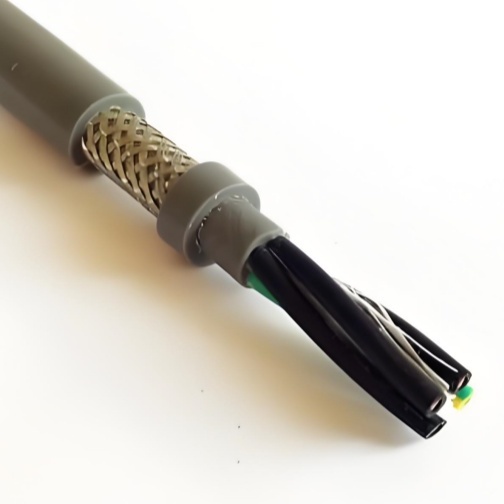
- Overall shield (optional): Tinned copper braid over entire assembly
- Outer jacket: PVC or PUR
Why Power Cores Go Inside
The larger, heavier power cores are placed at the center of the cable for three reasons:
- Mechanical stability: The heaviest components at the center reduce cable vibration during rapid carrier movement
- Thermal management: Power cores generate the most heat. Placing them at the center allows heat to dissipate outward through the jacket rather than being trapped between insulation layers
- Bend stress distribution: The inner bend radius of the cable experiences the highest compressive stress. Larger power conductors, with their greater mechanical strength, withstand this better than thin signal conductors
Common Configurations
| Configuration | Power | Signal | Data | Typical Use |
|---|---|---|---|---|
| 4G1.5 + 8 × 0.5 | 4 × 1.5 mm² | 8 × 0.5 mm² | — | Standard servo motor (no encoder) |
| 4G2.5 + 2 × 0.5 | 4 × 2.5 mm² | 2 × 0.5 mm² | — | Motor + brake |
| 4G1.5 + 2 × (2×0.25) | 4 × 1.5 mm² | — | 2 × TP | Servo motor + encoder feedback |
| 4G2.5 + 4 × 0.5 + 2 × (2×0.25) | 4 × 2.5 mm² | 4 × 0.5 mm² | 2 × TP | Full servo: power + brake/thermal + encoder |
| 4G4 + 4 × 0.75 + 4 × (2×0.34) | 4 × 4 mm² | 4 × 0.75 mm² | 4 × TP | Multi-axis: shared power bus + individual encoder |
Voltage Class Separation
Combined cables contain conductors rated for different voltage classes. The design must maintain safe separation:
- 600/1 000 V power cores: Thicker insulation (0.5–0.8 mm) — rated for line-to-line voltage up to 1 000 V
- 300/500 V signal cores: Standard insulation (0.3–0.5 mm) — rated for control circuit voltage
- 300/300 V data pairs: Thin insulation (0.2–0.3 mm) — rated for low-voltage communication
Shield Design — Protecting Signal from Power
When power and signal conductors share the same cable, the power conductors are a built-in EMI source. The 400 V PWM waveform switching at 4–16 kHz couples directly into adjacent signal conductors through inter-conductor capacitance.
For combined cables with encoder/data pairs, each pair is individually foil-shielded — just like a stand-alone encoder cable. The overall braid shield provides a secondary ground reference. This dual-shield approach ensures that the encoder signal is protected from EMI originating both inside the cable (power conductors) and outside (adjacent machinery).
If no data pairs are included, a single overall braid shield is sufficient for general signal protection.
Why Choose Yichi Cable Combined?
- Custom configurations: Send us your wiring diagram or motor datasheet — we design the cable to match. No "close enough" off-the-shelf compromises
- Layer-separated stranding: PET fleece between every voltage class is standard — not an option. Protects both electrical safety and signal integrity
- Individual pair shielding: Data pairs are individually foil-shielded as standard in combined cables — not an extra-cost upgrade
- Pre-production drawing approval: For custom configurations, we provide a cross-section drawing for your approval before production — you see exactly what you're getting
- Single-cable mindset: We design the cable to eliminate separate cables — not to be "one of several" in your carrier. The goal is ONE cable from panel to motor