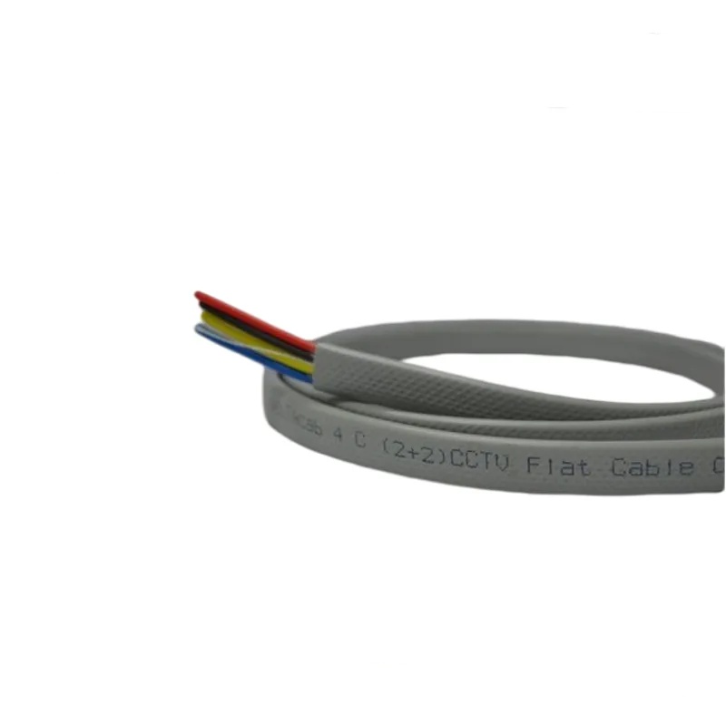
Detailed Description
The Flat Cable Advantage in Elevator Shafts
An elevator shaft is a narrow vertical space — typically 2.0–2.5 meters wide and 2.0–2.5 meters deep for a standard passenger elevator. Within this space must fit: the elevator car, guide rails, counterweight, counterweight guide rails, door operator, limit switches, traveling cable, and — in machine-room-less (MRL) elevators — the drive motor and control cabinet.
The traveling cable hangs in the gap between the car and the shaft wall. Its loop depth — how far the cable protrudes into the shaft from the wall — must not interfere with the moving car or counterweight. A round cable with a 20 mm OD, suspended in a loop with a 400 mm bend radius, occupies approximately 800 mm (2× radius) of shaft depth at the midpoint. If the clearance between the car and shaft wall is 150 mm, the cable loop protrudes 400 mm into a 150 mm gap — a problem solved only by increasing the shaft dimensions (expensive) or using a flat cable (practical).
A flat cable with a 3 mm thickness and the same 400 mm bend radius occupies the same 800 mm in the vertical plane, but only 3 mm in the horizontal plane — the cable loop lies flat against the shaft wall, taking almost no clearance from the car path. This is why flat traveling cables are the universal standard for elevator installations: not because round cables cannot be made flexible enough, but because only a flat cable fits in the available shaft space.
Core Count Evolution — Why Modern Elevators Need More Cores
A basic elevator from the 1980s required approximately 12–16 cores: car light, fan, door operator, call buttons, floor indicator, intercom, safety circuit. A modern elevator in a large commercial building requires 48–72 cores. The additional cores serve:
| Modern Function | Additional Cores | Signal Type |
|---|---|---|
| CCTV camera | 3–4 (coax or twisted pair + power) | Analog video or IP Ethernet |
| Access control card reader | 3–4 (power + RS-485 data) | Digital serial |
| Destination dispatch keypad | 4–6 (power + CAN bus data) | CAN bus |
| Emergency auto-dialer | 2 (telephone line) | Analog voice |
| Load weighing sensor | 3–4 (power + 4–20 mA signal) | Analog current loop |
| BMS interface | 2 (RS-485 Modbus) | Digital serial |
| Digital information display | 3–4 (power + data) | Digital serial/parallel |
| Audio/voice announcement | 2–3 (audio signal) | Analog audio |
| Wi-Fi access point | 2 (PoE power + data) | Ethernet |
| Spare (mandatory) | 5–10% of total | — |
This explains the upward trend in core counts — 72-core traveling cables are no longer exceptional for large commercial elevators. At the other end of the market a home lift or dumbwaiter still needs only 8–12 cores, so a single flat cable family has to span a very wide range.
Core Count Selection by Elevator Type
Core count is the first specification to fix, because it follows from the elevator's function set rather than from the building's height. The table below maps common elevator types to their usual flat traveling cable core count:
| Elevator Type | Floors | Typical Core Count | Key Functions |
|---|---|---|---|
| Home / residential elevator | 2–4 | 8–12 | Car light, door operator, call buttons, intercom, safety circuit |
| Dumbwaiter | 2–4 | 8–12 | Door interlock, call/send signal, safety circuit |
| Low-rise passenger (apartment) | 4–8 | 16–24 | + Floor indicator, emergency light/alarm, fan |
| Mid-rise passenger (office) | 8–20 | 24–36 | + Access control, load weighing, inspection control |
| Mid-rise service/freight | 4–10 | 20–30 | + Heavy-duty door operator, goods weighing |
| Accessibility platform lift | 1–2 | 8–12 | Door interlock, call station, safety circuit, emergency stop |
| High-rise passenger | 20–60+ | 48–72 | + CCTV, destination dispatch, BMS interface, information displays |
Specify at least 10% spare cores. The marginal cost of extra cores at the manufacturing stage is small, and it is prohibitive if the cable has to be replaced later because the building added a CCTV system or a load-weighing function.
Suspension height follows the same logic. Standard mid-rise shafts are served by 2–4 galvanized steel suspension wire ropes rated to 80 m, carrying the cable's self-weight so the copper conductors never act as a load-bearing member. High-rise shafts to 150 m use 2–6 suspension wires with the number and diameter matched to the suspended cable weight.
Installation Practices That Extend Cable Life
An elevator traveling cable that is correctly specified but incorrectly installed will fail prematurely. Three installation points matter:
1. Midpoint Suspension Loop Radius
The cable bends at the shaft midpoint where it transitions from the fixed shaft wall to the moving car. The minimum bend radius — typically 400 mm for a standard traveling cable — must be maintained. A tighter radius concentrates bending stress and significantly reduces cable life. The suspension bracket must be positioned to maintain the specified minimum radius at all car positions.
2. Steel Wire Anchorage
The steel suspension wires must be independently anchored — not simply clamped with the cable jacket. The anchorage must transfer the full suspended cable weight to the building structure (shaft midpoint) and car frame (car top). A loose or slipping steel wire anchorage transfers the load to the copper conductors — the failure mode is not immediate but progressive, appearing as intermittent open circuits after months of service.
3. Service Loop at Terminations
At both the shaft midpoint connection box and the car top junction box, the copper conductors must have a service loop — 50–100 mm of slack beyond the terminal block. This slack accommodates thermal expansion, building settlement, and minor cable movement without pulling on the terminations. Conductors terminated under tension will eventually pull out of the terminal or break at the termination point.
Yichi Flat Traveling Cable Manufacturing
- Parallel conductor alignment: Conductors are laid in parallel on a precision guide table with optical alignment sensors — pitch tolerance ±0.3 mm across the full cable width. Misalignment causes uneven bending stiffness and premature fatigue at the midpoint loop
- Steel wire tension equalized: All steel suspension wires are tensioned equally before jacket extrusion. Unequal tension means one wire carries more load than the others — it fatigues first, transferring its load to the remaining wires in a cascade failure
- Standardized core configurations: The 8–72 core range is organized into standard configurations that match common elevator controller wiring schemes, reducing installation time and wiring errors
- Jacket thickness profiled: The flat cable jacket is slightly thicker on the flat faces (where the cable bears against the shaft wall and car) and slightly thinner on the edges — the edge material adds bending stiffness without contributing to wear protection
- Bend life verified on production samples: Reciprocating bend test — 3 000 000 cycles at 400 mm bend radius. Acceptance: zero conductor breaks, <10% resistance increase, no jacket cracks visible under 10× magnification
- Jacket print marking: Cable identification, core count, voltage rating, and manufacturer marking printed on one flat face at 500 mm intervals, readable during installation and maintenance inspections