Elevator Traveling Control Cable — Multi-Core Flat Elevator Control Cable for Car Call, Floor Selection, Door Control, and Safety Circuit Signal Transmission in Elevator Shaft Traveling Cable Assemblies
Elevator & Lift Cables /Elevator & Lift Series

Elevator Traveling Control Cable — Multi-Core Flat Elevator Control Cable for Car Call, Floor Selection, Door Control, and Safety Circuit Signal Transmission in Elevator Shaft Traveling Cable Assemblies

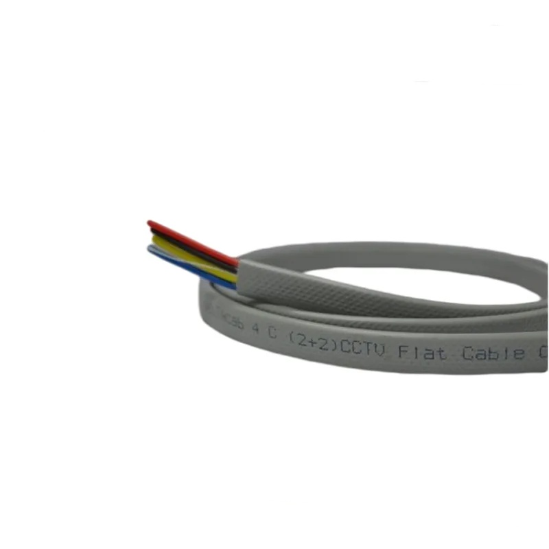
Elevator traveling control cable: multi-core flat control cable purpose-built for elevator car call, floor selection, door control, and safety circuit signal transmission. 0.5–1.5 mm² IEC 60228 Class 5 copper, 12–48 cores in parallel flat configuration with numbered identification per VDE 0293. PVC jacket. Integrated steel wire suspension. 300/500 V. Designed as the control-signal component of a complete elevator traveling cable assembly — carries all command, indication, and safety signals between the elevator car and the controller. CE, RoHS compliant.

Key Features

Control-optimized conductor sizing (0.5–1.5 mm²) — efficiently sized for signal-level currents (10 mA–2 A); no oversized power conductors adding unnecessary weight
Flat parallel conductor layout — thin, space-efficient profile for integration into the elevator shaft alongside power traveling cables
12–48 cores in standard configurations — matched to common elevator controller I/O counts: car calls, floor selection, door control, safety circuits, indication
Numbered core identification per VDE 0293 — permanent print marking on every core; fast, error-free termination at car operating panel and controller terminal strips
Integrated galvanized steel wire suspension elements — carry cable self-weight for shaft heights up to 80 meters
IEC 60228 Class 5 finely stranded copper — designed for millions of bending cycles at the shaft midpoint suspension point
Flame-retardant PVC jacket (IEC 60332-1-2) — standard material for elevator shaft installations
CE, RoHS compliant; ISO 9001 manufactured

Applications

Elevator car call and floor selection — transmits button press signals from the car operating panel to the elevator controllerElevator door control — door open, door close, door safety edge, and door lock safety circuit signalsCar position indication — floor position data from controller to car digital display and voice annunciatorElevator safety circuits — door lock series loop, overspeed governor, and emergency stop signalsCar top inspection control — inspection station control signals from car top to controller during maintenance and testingElevator modernization control — replacement control cable for older elevator control systems during modernization upgrades

Technical Specifications

Conductor Material Bare copper, IEC 60228 Class 5 finely stranded
Conductor Cross-Section 0.5 mm², 0.75 mm², 1.0 mm², 1.5 mm²
Number of Cores 12, 16, 20, 24, 30, 36, 40, 48
Core Identification Number-printed per VDE 0293; color coding on request
Core Insulation PVC (TI2 per VDE 0281)
Core Layout Parallel, side-by-side single-plane array
Steel Wire Suspension 2–4 galvanized steel wires (1 770 N/mm²); distributed across cable width
Outer Jacket PVC ST2; 1.5–2.0 mm; black or grey
Rated Voltage (U₀/U) 300/500 V
Test Voltage 2 000 V AC, 5 minutes
Temperature -15°C to +70°C (fixed); -5°C to +50°C (flexing)
Maximum Suspension Height Up to 80 meters
Bending Life >3 000 000 cycles at 400 mm bend radius
Flame Retardant IEC 60332-1-2
Certifications CE, RoHS

Detailed Description

Control vs Power — The Separation Argument

A combined elevator traveling cable carries both power conductors (1.5–2.5 mm² for car lighting, fan, door operator motor) and control conductors (0.5–1.5 mm² for signals) in one flat cable. This is the most common configuration for standard elevators — one cable, one installation, one set of terminations.

However, there are three reasons why a dedicated control traveling cable — separate from the power cable — is specified in certain applications:

1. Electrical Noise Isolation

A door operator motor draws 2–5 A at 220 V AC. When it starts and stops, it generates voltage transients that couple into adjacent conductors through parasitic capacitance. If these adjacent conductors carry the car call button signals — typically 24 V DC pulled up to 10 kΩ at the controller input — a transient can falsely trigger a floor call. A separate control cable, physically separated from the power cable in the shaft by 50–100 mm, eliminates this coupling path.

2. Modernization Flexibility

When modernizing an older elevator, the power requirements often change (new energy-efficient LED lighting replacing incandescent, new VFD door operator replacing AC motor). A separate control cable can remain in place while only the power cable is replaced — reducing modernization cost and downtime.

3. Controller Compatibility

Some elevator controllers — particularly older relay-logic and early solid-state controllers — require a specific core allocation and conductor cross-section that differs from the combined cable standard. A dedicated control cable can be specified to match the controller exactly, without compromise to accommodate power conductors.

Signal Allocation in a 24-Core Control Cable

A typical 24-core elevator control cable allocation for a mid-rise passenger elevator with collective-selective control:

Signal GroupCoresCross-SectionSignal Type
Car calls (floor buttons)80.5 mm²24 V DC, common return
Door open / door close20.75 mm²24 V DC or 110 V AC
Door safety edge20.5 mm²NC safety circuit, series loop
Floor position indication30.75 mm²Binary coded or serial data
Car position (selector)30.75 mm²Binary coded floor level
Intercom audio20.5 mm²Analog audio, shielded pair
Inspection control30.75 mm²Up/down/common
Spare10.75 mm²Future use

For CAN bus or serial communication elevators, 2–4 cores (0.5 mm²) are allocated to the data bus, typically with twisted pair construction for noise immunity.

Yichi Control Cable Manufacturing

  • Conductor sizing matched to signal current: Control conductors are sized for actual signal currents, not arbitrarily oversized. A 0.5 mm² conductor safely carries 3 A — far more than the 10–100 mA typical of elevator control signals. Oversizing adds weight, increases cable dimensions, and contributes nothing to electrical performance
  • Core numbering sequence logical for elevator wiring: Core numbers follow a logical grouping sequence (car calls grouped, door controls grouped, safety circuits grouped) rather than simple sequential numbering. This reduces wiring errors during installation
  • Steel wire suspension elements corrosion-protected: Galvanized steel wires are additionally coated with a thin PVC or PE layer where they exit the cable jacket at the anchorage points — preventing corrosion at the most vulnerable point, the jacket-to-air transition
  • Flame retardancy verified: PVC jacket compound tested per IEC 60332-1-2 on every production batch. The elevator shaft is a vertical fire propagation path — cable flame retardancy is a building safety requirement, not optional

Product Inquiry

Product: Elevator Traveling Control Cable — Multi-Core Flat Elevator Control Cable for Car Call, Floor Selection, Door Control, and Safety Circuit Signal Transmission in Elevator Shaft Traveling Cable Assemblies

Add technical specifications (optional)

The more detail you provide, the faster and more accurate our quotation.

No file chosen

PDF, Office, image or CAD file — up to 5 MB

Need Help?

Certifications

ISO 9001
Quality
CE
European
RoHS
Environmental
TÜV
Certification

Need a Quote for This Product?

Send us your requirements and receive a detailed quotation within 24 hours.