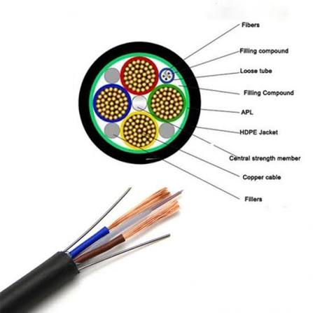
Fiber Optic Composite Power Cable — Single-Mode and Multi-Mode Fiber Optic Elements Integrated with Copper Power and Control Conductors in a Single PUR/PE Sheathed Composite Cable for Remote CCTV, Distributed I/O, Outdoor Equipment, and Long-Distance Combined Power + Data Transmission over a Single Cable Route
Industrial, Mining & Control Cables /Fiber Optic Composite

Fiber Optic Composite Power Cable — Single-Mode and Multi-Mode Fiber Optic Elements Integrated with Copper Power and Control Conductors in a Single PUR/PE Sheathed Composite Cable for Remote CCTV, Distributed I/O, Outdoor Equipment, and Long-Distance Combined Power + Data Transmission over a Single Cable Route

Fiber optic composite power cable: SM/MM fiber + copper power 0.6/1 kV + control in one PUR/PE jacket. Fiber in gel-filled SS loose tube. For remote CCTV, distributed I/O, outdoor equipment, combined power + fiber data transmission. Up to 24 fibers, 1.5-35 mm² power. CE, RoHS.

Key Features

Integrated single-mode (G.652D) and/or multi-mode (OM3/OM4) optical fibers + copper power conductors + optional control/signal cores in a single composite cable — one cable trench, one cable pull, one cable route for the complete power and data connection to remote equipment
Optical fibers in gel-filled stainless steel loose tube — the fibers are protected from moisture (gel filling), crush (SS tube rated >4 000 N/100 mm), and the mechanical stress of cable installation (bending, pulling, vibration); the loose tube is integrated into the core assembly at a position that minimises the fiber strain during cable bending
Single-mode (G.652D, 9/125 μm) for long-distance data backhaul — 1 310 nm / 1 550 nm operation, ≤0.35 dB/km attenuation; for CCTV camera data links, remote I/O communication, and SCADA networks over distances of 200 m to 50 km where copper Ethernet (100 m limit) is not feasible
Multi-mode (OM3/OM4, 50/125 μm) for short-reach, high-bandwidth data — 850 nm operation, ≤2.5 dB/km attenuation; for intra-building and campus data links where the lower-cost multi-mode transceivers provide cost savings over the 200–500 m typical reach
Copper power conductors — 0.6/1 kV XLPE insulated, Class 2 or Class 5 copper, 1.5–35 mm²; the power conductors deliver the equipment's operating power (24 V DC, 48 V DC, or 230 V AC) to the remote device, eliminating the need for a local power supply at the device location
The composite cable eliminates the need for a local power source at the remote device — for a CCTV camera on a perimeter fence, an environmental monitoring station, or a remote gate controller, the composite cable delivers both the camera power and the fiber data link in a single infrastructure investment, avoiding the cost of a separate power cable trench or a local solar/battery power system
PE (polyethylene) or PUR (polyurethane) outer jacket — PE for direct burial and outdoor fixed installation (superior moisture resistance and UV stability for 30+ year service life); PUR for dynamic applications (cable reeling, drag chain, robot arm) where flexibility and abrasion resistance are required
Water-blocked construction — water-swellable tapes and yarns in the core interstices prevent water migration along the cable if the outer jacket is damaged; essential for buried and outdoor installations where groundwater ingress can reach the optical fibers and copper conductors

Applications

Remote CCTV camera — composite cable from the control room to a CCTV camera on a perimeter fence, gate, or remote building; the fiber carries the camera's video data back to the NVR and the copper conductors power the camera, eliminating the need for a local power supply or a PoE extender beyond the 100 m Ethernet limitDistributed I/O and remote terminal units (RTU) — composite cable connecting a distributed I/O rack or RTU at a remote location (pump station, valve pit, tank farm) back to the control room; the fiber carries the SCADA or Ethernet data and the copper conductors power the RTU and its connected instrumentsWind turbine tower communications — composite cable from the tower base to the nacelle, carrying the fiber optic SCADA and condition monitoring data link and the copper power for the tower's aviation warning lights, service sockets, and auxiliary equipmentRailway and highway roadside equipment — composite cable for variable message signs, traffic monitoring cameras, weather stations, and emergency telephones along roads and railways where the cable is buried in the verge or installed in roadside duct and must deliver both power and fiber data over long distancesMining and tunnel communications — composite cable for the fiber optic backbone and equipment power supply along mine roadways and tunnels; the cable is installed on the tunnel wall or in the cable hangers and carries the site-wide communication network and the power for distributed network switches and wireless access pointsSolar farm monitoring — composite cable from the inverter stations to the central control building, carrying the fiber optic SCADA ring and the copper power for the inverter's control electronics and communication equipment

Technical Specifications

Fiber Type — Single-Mode (SM) ITU-T G.652D; 9/125 μm core/cladding; ≤0.35 dB/km at 1 310 nm, ≤0.22 dB/km at 1 550 nm; for long-distance (>2 km) data links
Fiber Type — Multi-Mode (MM) OM3 (50/125 μm, ≤2.5 dB/km at 850 nm, ≥1 500 MHz·km bandwidth) or OM4 (50/125 μm, ≤2.5 dB/km, ≥3 500 MHz·km); for short-reach, high-bandwidth data links (<500 m)
Fiber Count 4, 6, 8, 12, 24 fibers; the fiber count includes spare fibers for future expansion (typically 25–50% spare capacity)
Fiber Protection Gel-filled stainless steel loose tube, OD 2.0–3.0 mm; crush resistance >4 000 N/100 mm; the gel filling prevents moisture ingress and provides vibration damping for the fibers
Fiber Position in Core Assembly The SS loose tube is positioned in the centre or near-centre of the core assembly, where the bend radius is largest and the compression from the outer layers is minimised; the fiber strain during cable bending is controlled by the excess fiber length (EFL) in the loose tube — typically 0.1–0.3% excess length relative to the tube
Power Conductors — Copper IEC 60228 Class 2 or Class 5; 1.5, 2.5, 4, 6, 10, 16, 25, 35 mm²; XLPE insulation (90°C), 0.6/1 kV rated
Core Count — Power 2-core (DC supply positive + negative), 3-core (single-phase L+N+PE), 4-core (3P+PE), 5-core (3P+N+PE) per the equipment's supply requirement
Control Cores (Optional) 0.5–2.5 mm²; 300/500 V rated; for auxiliary equipment control and monitoring signals
Outer Jacket — PE (Standard) PE ST7; black; UV-stabilised; for direct burial and outdoor fixed installation; superior moisture resistance over 30+ year service life
Outer Jacket — PUR (Dynamic) PUR TMPU; black; for cable reeling, drag chain, and mobile equipment applications
Water Blocking Water-swellable tapes under the jacket and water-swellable yarns in the core interstices for longitudinal water blocking per IEC 60794-1-2
Fiber Attenuation — After Cable Manufacturing ≤0.35 dB/km (SM at 1 310 nm) + ≤0.05 dB/km added attenuation from the cabling process; the fiber attenuation is measured by OTDR on every fiber before and after the cabling process to verify that the cabling has not introduced additional loss
Temperature — PE Jacket -40°C to +80°C
Minimum Bend Radius — Installation 20× cable OD (the fiber loose tube limits the bend radius — tighter bends can increase the fiber attenuation or cause fiber breakage)
Minimum Bend Radius — Fixed 15× cable OD
Maximum Pulling Tension Determined by the fiber loose tube's maximum strain limit (typically 0.2–0.3% elongation); pulling by the jacket using a cable stocking
Flame Retardant PE is not inherently flame-retardant; for indoor building installation, specify an LSZH-jacketed composite cable
Certifications CE; RoHS; fiber attenuation test report (OTDR) per fiber provided with each cable drum; ISO 9001 manufactured

Detailed Description

What Is Fiber Optic Composite Power Cable?

A fiber optic composite power cable integrates optical fibers (for data communication) and copper power conductors (for equipment power supply) in a single cable — one infrastructure investment, one trench, one cable for the complete connectivity to remote equipment. It solves the fundamental limitation of copper-only outdoor data cables: Ethernet over copper is limited to 100 m by the IEEE 802.3 standard, and extending beyond this requires either a PoE extender (with its own power supply and weatherproof enclosure) or a local power source at the remote device (mains power or solar/battery). The fiber optic composite cable eliminates both — the fiber provides the data link over kilometers, and the copper conductors provide the device power from the central location.

Why Choose Yichi Fiber Optic Composite Power Cables

  • Single-mode and multi-mode fiber options — select for the data link distance and bandwidth: SM (G.652D) for long-distance data backhaul over 200 m to 50 km; MM (OM3/OM4) for short-reach, high-bandwidth links within a building or campus where the lower transceiver cost is a factor. Both fiber types available in the same composite cable construction
  • OTDR-tested fiber — attenuation verified before and after cabling: Every fiber in every production length is tested with an OTDR at 1 310 nm and 1 550 nm (SM) or 850 nm and 1 300 nm (MM). The attenuation before cabling (fiber on the bobbin) and after cabling (fiber in the finished cable) is recorded. The added attenuation from the cabling process must be <0.05 dB/km — demonstrating that the fiber has not been strained or micro-bent during the cable manufacturing
  • Gel-filled stainless steel loose tube — crush-proof, waterproof fiber protection: The SS tube withstands >4 000 N/100 mm crush force and the gel filling prevents water ingress. The tube is positioned at the optimal radial location in the core assembly to minimise fiber strain during cable bending — verified by OTDR measurement at the minimum bend radius
  • PE jacket for direct burial — 30+ year underground service life: The PE ST7 outer jacket is the preferred sheath for buried composite cable because it provides the best moisture barrier and chemical stability in soil. The cable is water-blocked with swellable tapes and yarns for longitudinal water protection in the event of jacket damage

Single-Mode and Multi-Mode Fiber Selection

The composite cable is built around either single-mode or multi-mode optical fiber, selected for the distance and bandwidth of the data link. Single-mode fiber (ITU-T G.652D, 9/125 um) operates at 1 310 nm and 1 550 nm with attenuation no greater than 0.35 dB/km, and carries the long-distance data backhaul for links from 200 m out to 50 km where copper Ethernet is limited to 100 m. Multi-mode fiber (OM3 or OM4, 50/125 um) operates at 850 nm with attenuation no greater than 2.5 dB/km and bandwidth of 1 500 MHz·km (OM3) or 3 500 MHz·km (OM4); it serves the short-reach, high-bandwidth links within a building or campus where lower-cost transceivers apply over the typical 200-500 m reach. Both fiber types are available in the same composite construction, with a fiber count of 4, 6, 8, 12, or 24 and spare capacity of 25-50% for future expansion.

Fiber Protection — Gel-Filled Stainless Steel Loose Tube

The optical fibers sit in a gel-filled stainless steel loose tube with an outer diameter of 2.0-3.0 mm and a crush resistance above 4 000 N/100 mm. The gel filling blocks moisture ingress and damps vibration, and the steel tube protects the fibers from the crush and mechanical stress of installation and operation. The loose tube is placed at or near the centre of the core assembly, where the bend radius is largest and the compression from the outer layers is lowest. The fiber strain during bending is controlled by the excess fiber length in the loose tube, typically 0.1-0.3% relative to the tube, and is verified by OTDR measurement at the minimum bend radius. After the cabling process the added attenuation must remain below 0.05 dB/km, confirming that no strain or micro-bend has been introduced.

Copper Power Conductors and Remote Device Supply

The copper power conductors are XLPE-insulated, IEC 60228 Class 2 or Class 5, rated 0.6/1 kV, in cross-sections from 1.5 to 35 mm², with a core count of 2, 3, 4, or 5 to match the equipment supply (DC pair, single-phase L+N+PE, 3P+PE, or 3P+N+PE). These conductors deliver the remote device's operating power, 24 V DC, 48 V DC, or 230 V AC, so a CCTV camera, environmental station, or gate controller is powered from the central location without a local mains supply or a solar/battery system. Optional control cores (0.5-2.5 mm², 300/500 V) carry auxiliary control and monitoring signals.

Jacket Selection — PE for Burial, PUR for Dynamic Use

The outer jacket is PE or PUR. PE (ST7, black, UV-stabilised) is the sheath used for direct burial and outdoor fixed installation because of its moisture resistance over a 30+ year service life; its temperature range is -40°C to +80°C. PUR (TMPU, black) is specified for dynamic applications, cable reeling, drag chain, and robot arm, where flexibility and abrasion resistance are required. The core is water-blocked with swellable tapes and yarns for longitudinal water protection if the jacket is damaged. PE is not inherently flame-retardant; for indoor building routing an LSZH-jacketed composite is specified.

Product Inquiry

Product: Fiber Optic Composite Power Cable — Single-Mode and Multi-Mode Fiber Optic Elements Integrated with Copper Power and Control Conductors in a Single PUR/PE Sheathed Composite Cable for Remote CCTV, Distributed I/O, Outdoor Equipment, and Long-Distance Combined Power + Data Transmission over a Single Cable Route

Add technical specifications (optional)

The more detail you provide, the faster and more accurate our quotation.

No file chosen

PDF, Office, image or CAD file — up to 5 MB

Need Help?

Certifications

ISO 9001
Quality
CE
European
RoHS
Environmental
TÜV
Certification

Need a Quote for This Product?

Send us your requirements and receive a detailed quotation within 24 hours.