Detailed Description
What Is RVSP Cable?
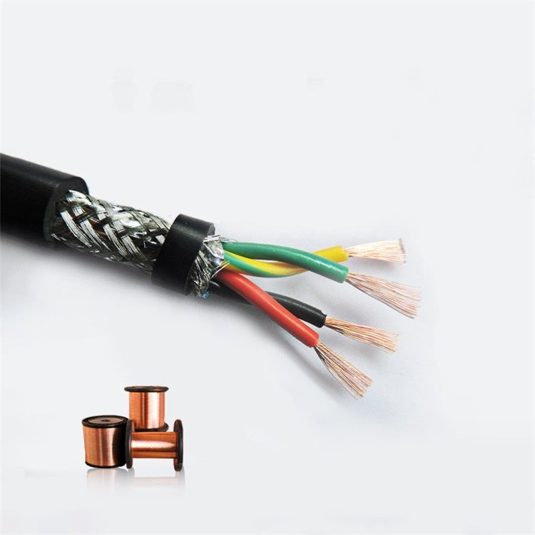
RVSP is a widely used designation in Chinese and Asian industrial cable markets for a flexible, twisted-pair, shielded signal cable. The designation breaks down as:- R (Ruan / 软) — flexible stranded copper conductor, IEC 60228 Class 5
- V (PVC / 聚氯乙烯) — polyvinyl chloride insulation on each core
- S (Shuang jiao / 双绞) — twisted pair construction; cores are paired and twisted
- P (Ping bi / 屏蔽) — tinned copper wire braid shield over the core assembly
Unlike TRVVSP (the drag-chain-rated variant), RVSP is designed for fixed installation and occasional repositioning — not for continuous flex in a cable carrier. The PVC insulation and jacket provide adequate flexibility for routing through conduit, cable trays, and control panels, but the materials are not optimized for millions of bending cycles.
RVSP vs TRVVSP — When to Use Each
| Criteria | RVSP | TRVVSP |
|---|---|---|
| Design intent | Fixed installation, occasional repositioning | Continuous flex in drag chains and cable carriers |
| Conductor class | IEC 60228 Class 5 (flexible stranded) | IEC 60228 Class 6 (extra-fine stranded) |
| Core insulation | PVC (εr ≈ 3.5–4.5) | PE or PP (εr ≈ 2.3) — lower capacitance for high-speed signals |
| Pair shielding | Overall braid only (no per-pair foil) | Individual foil per pair + overall braid |
| Crosstalk protection | Moderate — staggered lay lengths reduce coupling | ≥50 dB pair-to-pair — foil-per-pair eliminates capacitive crosstalk |
| Capacitance (core-core) | ≤120 pF/m | ≤60 pF/m |
| Flex life | Not rated for continuous flex | 5–10 million cycles |
| Temperature (moving) | Not rated — fixed installation only | -10°C to +70°C (PVC), -40°C to +80°C (PUR) |
| Cost | Lower | Higher (more manufacturing steps, PE insulation, dual shielding) |
| Best application | Panel wiring, conduit, cable tray, junction-box to field-device | Cable carrier between moving axis and control cabinet |
Core Count and Configuration Guide
RVSP cables are typically built in twisted-pair multiples, with or without additional single cores:
| Core Configuration | Typical Cross-Section (mm²) | Approx. OD | Application |
|---|---|---|---|
| 2 × 0.30 | 1 pair | 4.2 mm | Single RS-485 link, short run |
| 2 × 0.50 | 1 pair | 4.8 mm | Standard RS-485 / MODBUS drop cable |
| 2 × 0.75 | 1 pair | 5.3 mm | Long-distance RS-485 (>500 m) |
| 4 × 0.50 | 2 pairs | 5.8 mm | Full-duplex RS-422 (TX+TX- + RX+RX-) |
| 6 × 0.50 | 3 pairs | 7.0 mm | Two RS-485 links + spare pair |
| 8 × 0.50 | 4 pairs | 7.8 mm | Multi-axis encoder (4 incremental encoders) |
| 12 × 0.50 | 6 pairs | 9.5 mm | Multi-channel analog input junction box |
| 16 × 0.50 | 8 pairs | 11.0 mm | DCS marshalling panel to field devices |
| 4 × 1.0 | 2 pairs | 6.5 mm | RS-485 with longer distance or higher power requirement |
| 4 × 1.5 | 2 pairs | 7.8 mm | Encoder feedback with power conductors |
Core identification follows a simple color scheme: each pair is typically black (A) and white (B), with consecutive pairs identified by jacket print or numbered tape. Custom color coding per DIN 47100 or customer specification is available.
Conductor Resistance and Voltage Drop
For long cable runs, conductor resistance determines the maximum usable distance. At the RS-485 receiver, the differential voltage must remain above the 200 mV receiver threshold after DC losses:
| Cross-Section | Conductor Resistance (Ω/km, max) | Voltage Drop per 100 m at 250 mA (pair, round-trip) | Max Recommended RS-485 Distance |
|---|---|---|---|
| 0.30 mm² | ≤69.2 | 3.46 V | 200 m |
| 0.50 mm² | ≤39.0 | 1.95 V | 500 m |
| 0.75 mm² | ≤26.0 | 1.30 V | 800 m |
| 1.0 mm² | ≤19.5 | 0.98 V | 1 000 m |
| 1.5 mm² | ≤13.3 | 0.67 V | 1 200 m (RS-485 standard limit) |
Values assume 250 mA signal current and a 5 V driver supply — actual usable distance also depends on data rate, cable capacitance, and termination quality. For distances beyond 1 200 m, use RS-485 repeaters; increasing the conductor cross-section alone cannot overcome the data-rate limitation.
Signal Types Supported by RVSP Cable
| Signal Type | Level / Protocol | Suitability | Notes |
|---|---|---|---|
| RS-485 | Differential, ±1.5 V min | ✅ Standard application | Single twisted pair + braid; 120 Ω termination at both ends |
| RS-422 (full duplex) | 2 × differential pairs | ✅ Suitable | Requires 4 cores (2 pairs); TX and RX pairs should be adjacent for matched propagation delay |
| RS-232 (short distance) | Single-ended, ±5–15 V | ⚠️ Acceptable for <15 m | Single-ended signals do not benefit from twisted pair C-MRR; use only where RS-232 is unavoidable |
| 4–20 mA analog | Current loop, DC–10 Hz | ✅ Excellent | Twisted pair cancels 50/60 Hz common-mode induced voltage on long runs |
| 0–10 V analog | Voltage, high impedance | ⚠️ Usable <50 m | High-impedance voltage signals are susceptible to capacitive coupling; 4–20 mA current loop preferred where possible |
| 24 V DC digital I/O | PNP / NPN, <100 Hz | ✅ Suitable | Inductive kickback from relay coils and solenoids on adjacent cores can couple through inter-core capacitance; use suppression diodes at inductive loads |
| Thermocouple (mV) | ±0–50 mV DC | ⚠️ Requires care | Type K thermocouple output is ~40 μV/°C; PVC insulation triboelectric noise during cable movement can mask the signal — secure cable against vibration |
Installation Guidelines
- Separation from power: Maintain ≥200 mm separation from unshielded power cables (400 V motor, VFD output). Inside the same cable tray, use a grounded metallic divider. For parallel runs exceeding 5 m alongside power, consider upgrading to a double-shielded cable (foil-per-pair + braid)
- Bend radius: 6× cable OD for fixed installation routing. Do not bend below 0°C — PVC stiffens and may crack
- Shield termination: Connect the drain wire to ground at the control panel end only (single-point). Leave the field-device end floating — this prevents 50/60 Hz ground-loop currents from flowing in the shield. For RS-485, the shield should NOT be used as the signal common (0 V reference) — run a dedicated signal common conductor
- Avoid coiling excess cable: Excess cable coiled in a loop acts as an inductive pickup. Cut to length or lay excess in a figure-8 pattern to minimize loop area
- Pull tension: Do not exceed 50 N/mm² of total copper cross-section during installation to avoid conductor elongation and insulation thinning
Why Choose Yichi Cable RVSP?
- Conductor resistance verified per IEC 60228: Every production batch is sampled and tested for DC resistance at 20°C. A conductor that does not meet the Class 5 resistance limits — whether due to incorrect stranding or copper quality — is rejected before it becomes your noise or voltage-drop problem
- Braid coverage consistency: The tinned copper braid is woven on precision braiding machines with closed-loop tension control, ensuring ≥80% optical coverage along the full cable length. Spotty braid coverage — a common issue with manual or poorly maintained braiders — creates gaps where EMI couples directly into the pairs
- Staggered lay lengths verified: Adjacent pairs are built with different twist lay lengths. This is documented in the production record. If all pairs have the same twist pitch, periodic alignment creates crosstalk hot-spots along the cable — a subtle defect that manifests as intermittent communication errors on one channel when another channel transmits
- Full electrical test data: Insulation resistance (≥5 GΩ·km), capacitance (≤120 pF/m core-core), and 1 500 V AC HV test results are recorded per production length and available with delivery. No black-box cable where you have to trust a datasheet
- Global supply, Asian manufacturing quality: Standard configurations ship in 7–15 days. Custom core counts and cross-sections in 2–3 weeks with full test documentation. CE and RoHS certified for EU market access