Detailed Description
Why Shield a Drag Chain Cable?
Every variable frequency drive, servo amplifier, contactor, and switching power supply radiates electromagnetic interference. In a cable carrier, power and signal cables often run side by side — separated by millimeters, not meters.
Without a shield, the power cable's switched voltage waveform capacitively couples into adjacent signal cables. A 400 V PWM waveform with 5 kV/μs dv/dt can induce several volts of noise into an unshielded 4–20 mA sensor loop — enough to cause false readings or controller faults.
A braided copper shield around the signal cable creates a grounded conductive barrier. The induced noise current flows through the shield to ground rather than coupling into the signal conductors. It is the most cost-effective EMI solution for standard industrial carriers.
TRVVP — The "P" Makes the Difference
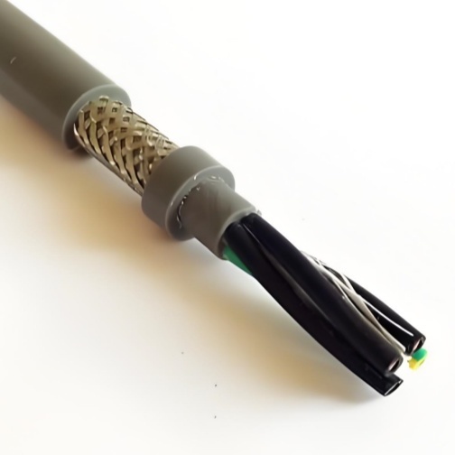
TRVVP is TRVV (standard drag chain cable) with one added letter: P for shielded (from the German "P" designation). The construction is otherwise identical — same conductors, same insulation, same jacket. The shield is an additional layer between the core assembly and the outer jacket.
This simplicity is its strength. The TRVVP uses the same proven TRVV mechanical design, with a single braid layer added for EMI protection. No complex multi-layer shield systems, no exotic materials — just a reliable copper braid that does its job.
Shield Grounding — The #1 Installation Mistake
The most common shielded cable complaint — "we installed shielded cable and still have noise" — is nearly always a grounding problem, not a cable problem.
Correct: Both-End Grounding (for most applications)
Connect the shield to ground at both the drive/controller end and the motor/sensor end. This creates a continuous ground path that shunts noise current away from the signal conductors. For frequencies above 100 kHz (typical of VFD switching harmonics), both-end grounding is the only effective method.
Requirement: Both grounding points must be at the same potential. If the motor frame and the control cabinet have different ground potentials, the shield will carry 50/60 Hz ground loop current — adding noise instead of removing it.Alternative: Single-End Grounding (for low-frequency only)
Connect the shield at the controller end only. Leave the field end ungrounded. This eliminates ground loop current but only works for frequencies below ~100 kHz. At VFD switching frequencies, the ungrounded end acts as an antenna.
The ground loop check:
- With the machine powered but the drive disabled, measure AC voltage between the two proposed shield grounding points
- If the measured voltage is < 0.5 V AC, both-end grounding is safe
- If > 0.5 V AC, investigate the ground bonding between the two points before both-end grounding
Practical termination:
- Use 360° EMC cable glands — the shield makes full circumferential contact with the gland body
- Do NOT use pigtail drain wires as the primary shield connection — a 50 mm pigtail adds ~50 nH inductance, effectively disconnecting the shield at frequencies above 30 MHz
- If a drain wire is used (for convenience), it must be as short as possible (< 25 mm) and supplementary to 360° contact
Carrier Routing — Power and Signal Separation
In an ideal world, shielded power cables and shielded signal cables would run in separate carriers. In the real world, machine designers put everything in one carrier. When this happens:
- Maximum separation: Power cables on one side of the carrier, signal cables on the other. Use carrier dividers if available
- Cross at 90°: If cables must cross paths in the carrier (e.g., at the fixed end where they exit to different destinations), ensure they cross at right angles — never run parallel
- Ground all shields: Every shielded cable in the carrier must have its shield grounded at both ends. An ungrounded or single-end-grounded shield in a shared carrier acts as a capacitive coupler, injecting noise into grounded-shield cables
- No spare conductors: Unused cores in multi-conductor shielded cables should be grounded at one end. Floating conductors inside a shield create internal capacitive coupling
When Shielded Is Not Enough — Upgrade Path
This cable is designed for moderate EMI environments — one VFD nearby, a few contactors, standard factory electrical noise. If your application exceeds these limits:
| Symptom | Likely Cause | Upgrade To |
|---|---|---|
| Intermittent encoder faults | VFD switching noise coupling through braid at high frequency | Double-Shielded (foil + braid) |
| Shield braid visible through worn jacket | Excessive carrier wall friction | Wear-Resistant Drag Chain Cable |
| Shield fails (open circuit) before conductors | Braid fatigue from tight bends | Shielded High-Flex Cable |
| Noise on analog signals when carrier moves | Intermittent shield contact from flex | Flexible Shielded Drag Chain Cable (enhanced inner wrap) |
Why Choose Yichi Cable Shielded Drag Chain?
- Drain wire as standard: Every shielded cable includes a tinned copper drain wire — no extra cost, no special order
- PET fleece inner wrap: Protects the braid from abrading core insulation — included on all shielded cables, not an option
- Coverage verified per batch: Every production batch is tested for braid optical coverage — we publish the result
- Grounding application note: We provide installation-specific grounding recommendations with every order — two sentences in an email that can save hours of noise troubleshooting
- Upgrade path clarity: If standard shielded is not enough, we identify why and recommend the specific upgrade — not a generic "buy the more expensive one"