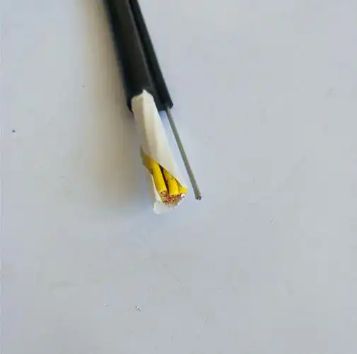
Detailed Description
Why a Single Steel Wire?
A standard (no steel wire) overhead crane control cable works well for short pendant drops — up to about 5 meters. In these applications, the combined weight of the cable and a lightweight pendant push-button station (1–3 kg) produces a tensile stress well within the copper conductors' elastic limit. The cable flexes, the pendant moves, and everything operates reliably for years.
The problem appears on taller cranes. A double-girder EOT crane in a heavy fabrication workshop may have a pendant drop of 10–15 meters. On a large gantry crane in a container yard, the drop can exceed 20 meters. At these lengths:
- The cable's self-weight alone exceeds 5–15 kg (depending on core count and cross-section)
- Add a heavy-duty pendant station with a metal enclosure (3–8 kg) and the total suspended load reaches 10–25 kg
- This sustained tensile load, applied 24/7 at the strain relief clamp, causes creep elongation in the copper conductors — they gradually neck down, increase in resistance, and eventually fracture at the point of maximum stress
One Wire vs Multiple Wires — The Design Choice
Why a single steel wire rather than multiple smaller wires? Three reasons:
1. Core Count Efficiency
A single central wire occupies one position in the geometric core layout. Multiple steel wires distributed in the outer layers would displace several copper cores — reducing the available signal count for the same cable diameter. For a 12-core cable with a single central steel wire, all 12 copper cores are available for control signals plus the steel wire doubles as the equipment ground. The alternative — two smaller steel wires in the outer layer — would displace 2 copper cores, leaving only 10 for signals.
2. Symmetrical Bending
A single central wire creates a perfectly symmetrical cable cross-section. When the cable bends at the pendant strain relief — the point of maximum flexing — the bending stress distributes evenly around the circumference. Multiple offset steel wires create an asymmetrical cross-section that bends preferentially in one direction, concentrating fatigue on a few copper conductors.
3. Termination Simplicity
One central steel wire requires one anchor point at each end. The strain relief clamp grips the steel wire directly, and all copper cores are terminated normally at the terminal block. Multiple steel wires would require a more complex clamping arrangement or individual anchor points — adding bulk, cost, and potential failure points.
Cable Construction Detail
The cross-section, from center to outside, is built in concentric layers:
| Layer | Component | Material | Function |
|---|---|---|---|
| Core (center) | Central steel wire | Galvanized steel, 1 770 N/mm² | Tensile load bearer + equipment ground conductor |
| Layer 1 | Copper control cores (first concentric ring) | Bare copper, IEC 60228 Class 5, numbered per VDE 0293 | Hoist up/down, trolley L/R, bridge F/R, E-stop, limit switch signals |
| Layer 2 | Copper control cores (outer concentric ring) | Bare copper, IEC 60228 Class 5 | Additional control signals; number of cores increases with core count specification |
| Filler | Non-hygroscopic filler elements | PP or jute | Fill interstices between cores for round, compact cross-section |
| Inner Sheath (optional) | Inner sheath | PVC or CR | Mechanical protection over core assembly; applied when specified |
| Outer Jacket | Outer jacket | PVC, CR, or PUR (1.2–2.5 mm) | Environmental protection; cable identification printed on jacket face |
The steel wire at the core is surrounded by copper control cores in one or two concentric layers, with filler elements filling the gaps. The entire assembly is optionally covered by an inner sheath, then the outer jacket.
Steel wire at center: Surrounded by the first concentric layer of copper control cores. Filler elements fill the interstices for a round, compact assembly. An optional inner sheath is extruded over the complete core assembly before the outer jacket is applied.Selecting the Steel Wire Diameter
The steel wire diameter is proportional to the expected suspended load and the core count:
| Pendant Drop | Cable Self-Weight (12-core, 1.5 mm²) | Pendant Station Weight | Total Load | Recommended Steel Wire Ø |
|---|---|---|---|---|
| <5 m | ~2 kg | 1–3 kg | 3–5 kg | 1.5 mm (standard) |
| 5–10 m | ~5 kg | 2–5 kg | 7–10 kg | 2.0 mm |
| 10–20 m | ~10 kg | 3–8 kg | 13–18 kg | 2.5 mm |
| >20 m | >15 kg | 5–10 kg | >20 kg | 3.0–4.0 mm |
The safety factor is typically 10:1 or higher — a 1.5 mm steel wire with a breaking load of ~250 kg supports a 3–5 kg working load at a safety factor of 50–80.
Comparison: With vs Without Steel Wire
| Parameter | Standard Control Cable | Single Steel Wire Control Cable |
|---|---|---|
| Central element | Filler or copper core | Galvanized steel wire |
| Tensile load path | Copper conductors | Steel wire |
| Max recommended pendant drop | ~5 m | >20 m (with appropriate steel wire Ø) |
| Equipment ground | Dedicated copper core | Steel wire (dual function) |
| Core count for same OD | n cores | n cores (steel wire replaces one filler, not a core) |
| Fatigue life at >10 m drop | Reduced — copper creep | Full — steel carries load |
| Cost | Baseline | +10–15% |
| Weight | Baseline | +5–8% |
Yichi Quality Notes
- Steel wire integrated in-house: The steel wire is cabled into the core assembly during our own stranding process — not added as an afterthought. Tensile testing per DIN EN 10002-1 verifies breaking strength before jacket extrusion
- Strain relief anchorage tested: Each production sample is subjected to a pull test at 2× rated working load for 1 hour — zero slippage at the steel wire anchor point is required
- Spark test + insulation resistance: Every drum is spark-tested at 2 500 V AC and insulation resistance measured between all conductors and the steel wire — ensuring no galvanic or insulation defects
- Marked for correct termination: The steel wire is identified with a yellow/green stripe or marking sleeve — installers immediately recognize it as both the tensile anchor point and the equipment ground conductor