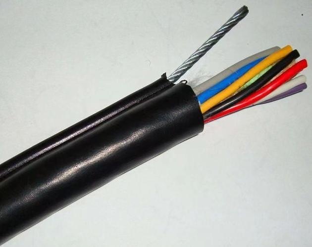
Detailed Description
Why Reinforce with Steel Wire?
Copper is an excellent electrical conductor, but it is a poor structural material for sustained tensile loads. Pure copper has a tensile strength of approximately 220 N/mm² — less than one-eighth of galvanized steel wire at 1 770 N/mm². More importantly, copper creeps under sustained load: a copper conductor under constant tension gradually elongates, reducing its cross-section, increasing its resistance, and eventually fracturing. This process takes months or years, but it is inevitable if the copper is the primary tensile load path.
Steel wire reinforcement transfers the mechanical load from the copper conductors to the steel. The copper conductors carry current; the steel wire carries tension. Each material does what it does best.
Three Reinforcement Configurations — Choosing the Right One
| Configuration | Steel Wire Placement | Best For | Typical Applications |
|---|---|---|---|
| Type A — Single Central Wire | Center of round core assembly | Vertical suspension; moderate tensile load | Pendant control (≤25 m drop); vertical shaft power; hoist reeling |
| Type B — Dual Edge Wires | Longitudinal edges of flat cable | Anti-twist; tensile + wear | Flat festoon cables; bridge crane festoon; conveyor cable trolley |
| Type C — Braid Layer | Steel wire braid between inner and outer sheath | Heavy tensile load; abrasion protection | Heavy-duty reeling; mining drag cables; marine cables; TBM cables |
Type A — Single Central Wire
The most common configuration for round cables. One galvanized steel wire runs straight through the center of the core assembly. The copper cores are stranded in concentric layers around it. Advantages: simple construction, symmetrical bending, steel wire can serve as equipment ground. Limitation: the single wire can only support a finite tensile load — for very heavy cables (≥35 mm², >50 m vertical drop), Type C may be required.
Type B — Dual Edge Wires
For flat cables. Two steel wires of equal diameter are embedded in the longitudinal edges of the flat cable cross-section. Advantages: provides both tensile strength and torsional stiffness (anti-twist), the wires act as sacrificial wear surfaces at the cable edges. Limitation: only works with flat cable geometry; not applicable to round cables.
Type C — Braid Layer
For the heaviest applications — large cross-section reeling cables, mining drag cables, tunnel boring machine cables. A layer of galvanized steel wire braid is applied between the inner and outer sheath. Advantages: extremely high tensile strength (distributed over the entire cable circumference), excellent abrasion resistance, provides a continuous ground/earth path. Limitation: heavier, more expensive, slightly larger OD for the same copper cross-section.
Termination — Anchoring the Steel Wire
The steel wire is only effective if it is properly anchored at both cable ends. A steel wire that slips in the termination transfers no load. Standard practice:
- At the pendant/control station end: The steel wire is clamped in a dedicated strain relief grip that is mechanically fixed to the pendant enclosure. The copper cores are terminated at the terminal block with a service loop (50–100 mm of slack) so that if the cable is pulled, the tension goes to the steel wire anchor, not the terminal block
- At the junction box/panel end: The steel wire is anchored to the cable gland or a separate strain relief bracket inside the enclosure. The gland must be rated for the steel wire diameter and must provide a positive clamp, not just a compression seal
Yichi Steel Wire Reinforced Cable Quality
- Steel wire tensile tested per DIN EN 10002-1: Every batch of steel wire is sampled and tensile tested. Breaking load, yield strength, and elongation are recorded. Wire that does not meet the specified 1 770 N/mm² minimum tensile strength is rejected
- Galvanizing quality verified: Zinc coating thickness is measured per ISO 2178. Minimum coating mass is 50 g/m² for indoor cables, 80 g/m² for outdoor/PUR cables. Inadequate galvanizing leads to steel wire corrosion inside the cable — invisible from the outside
- Strain relief anchor tested on finished cable: Pull-test at 2× rated working load for 1 hour — zero slippage at the steel wire anchor point is required. Test performed on every new cable design
- Spark test at full rated voltage: Every meter of finished cable is dry-spark-tested at the rated test voltage. The steel wire's electrical connection to ground during testing ensures that any insulation defect between a copper core and the steel wire is detected immediately