Detailed Description
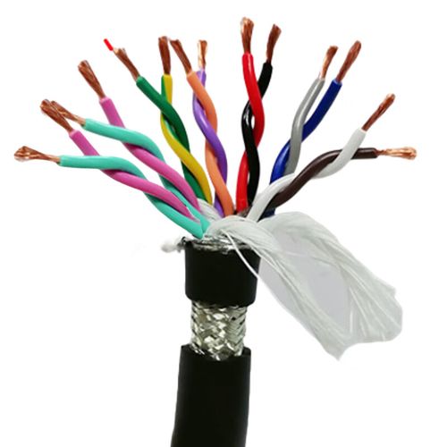
What Is Twisted Pair Shielded Signal Wire?
A twisted pair shielded signal wire is the cable type specifically optimised for low-level analog measurement — the category of industrial signal that demands the most from its cabling. While all shielded twisted pair cables reduce noise, a signal wire built for measurement applications distinguishes itself in three parameters:
- Insulation material — Polyethylene (PE) instead of PVC, reducing the dielectric constant from ~4 to ~2.3. This halves the pair capacitance, preserving signal bandwidth and minimising capacitive loading on high-impedance sensors
- Insulation resistance — ≥10 GΩ·km minimum (versus ≥5 GΩ·km for general-purpose signal cables). At the gigaohm level, leakage currents through the insulation are measured in picoamps — below the noise floor of all but the most sensitive laboratory instruments
- Capacitance matching — the insulation wall thickness and pair twist lay length are controlled to tighter tolerances so that all pairs in a multi-pair cable have matched capacitance. In a simultaneous-sampling data acquisition system, unmatched capacitance translates directly to channel-to-channel timing skew
PE insulation halves that cable capacitance, doubling the usable bandwidth — or, for the same bandwidth, doubling the permissible cable length.
Signal Wire vs Standard Shielded Cable — What Changes?
| Parameter | Standard Twisted Pair Shielded Cable | Twisted Pair Shielded Signal Wire |
|---|---|---|
| Core insulation default | PVC (εr ≈ 3.5–4.5) | PE (εr ≈ 2.3) |
| Capacitance (core-core, 0.50 mm²) | ≤120 pF/m | ≤60 pF/m |
| Insulation resistance (min) | ≥5 GΩ·km | ≥10 GΩ·km |
| Capacitance matching (pair-to-pair) | Not controlled | ≤5% variation across pairs |
| Conductor size range | 0.14–2.5 mm² | 0.14–1.0 mm² (optimised for signal, not power) |
| Max pair count | 24 pairs | 12 pairs (PE insulation is stiffer; higher pair counts increase OD sharply) |
| Temperature (fixed) | -20°C to +70°C (PVC jacket) | -40°C to +80°C (PE cores + PVC jacket) |
| Best application | General signal: RS-485, CAN, 4–20 mA, digital I/O | Precision measurement: RTD, thermocouple, strain gauge, accelerometer, mV-level analog |
| Cost premium | Reference | Moderate — PE insulation and tighter process controls add ~15–25% to material and testing cost |
The cost premium reflects real manufacturing differences — PE insulation requires different extrusion tooling and process parameters than PVC, and capacitance-matching requires individual pair testing rather than batch sampling. For applications where the measurement accuracy is limited by the sensor and electronics (not the cable), the standard cable is the rational choice. For applications where the cable is the limiting factor, the signal wire pays for itself in measurement performance.
Measurement Applications — How the Cable Affects Accuracy
RTD Temperature Measurement (Pt100, 4-Wire)
A Pt100 RTD changes resistance by ~0.385 Ω/°C. In a 4-wire measurement, the excitation current (typically 1 mA) flows through one pair, and the voltage drop across the RTD is sensed through a second pair. The sense pair carries negligible current, so its series resistance does not affect the measurement.
What does affect the measurement is:
- Thermoelectric EMF at the junction of the copper conductor and the RTD lead wire — this appears as a DC offset in series with the measured voltage. Using tinned copper conductors throughout the signal chain minimises dissimilar-metal junctions
- Capacitive coupling of 50/60 Hz mains voltage onto the sense pair — the shield intercepts this, but only if terminated correctly. A floating shield is no shield at all
- Leakage current through the insulation of the sense pair — PE's ≥10 GΩ·km insulation resistance means ≤10 nA leakage at 100 V, negligible compared to the 1 mA excitation
Thermocouple Extension
Thermocouples produce a voltage proportional to the temperature difference between the measurement (hot) junction and the reference (cold) junction. A Type K thermocouple generates approximately 40 μV/°C.
The single greatest cable-related error source in thermocouple measurement is thermoelectric EMF at the connector or terminal block. If the thermocouple wire is copper (as in a standard twisted pair cable), the copper-to-thermocouple-alloy junction at each terminal block creates an additional, unmeasured thermocouple. A 1°C temperature difference across that terminal block produces ~40 μV of error — equivalent to a 1°C measurement error for Type K.
The correct approach is to use thermocouple extension cable — conductors made from the same alloys as the thermocouple itself — from the sensor head to the measurement instrument. A shielded twisted pair signal wire with general-purpose copper conductors should only be used between the thermocouple transmitter (which converts the thermocouple voltage to 4–20 mA at the sensor head) and the PLC — not between the thermocouple and the transmitter.
Strain Gauge (Full Bridge, 350 Ω)
A 350 Ω strain gauge bridge with 2 mV/V sensitivity and 5 V excitation produces a full-scale output of 10 mV. For a 16-bit ADC with a ±10 mV input range, 1 LSB = 0.305 μV.
At this signal level:
- Cable capacitance forms a low-pass filter with the bridge output impedance (~350 Ω). A 100 m cable with 60 pF/m = 6 nF total → -3 dB at ~76 kHz. For static or quasi-static strain measurement (DC–100 Hz), this is irrelevant
- Triboelectric noise — charge generated by friction between the conductor and insulation when the cable is flexed — can produce voltage spikes that exceed the microvolt-level signal. PE insulation has lower triboelectric noise than PVC, which is one reason it is preferred for instrumentation
- Shield effectiveness — the cable shield must prevent capacitively-coupled 50/60 Hz from the environment from reaching the signal conductors. Even 1 μV of coupled mains hum is ~3 LSB on a ±10 mV, 16-bit measurement
Shield Current and Ground Loops in Measurement Systems
A ground loop occurs when the shield (or signal common) is connected to ground at more than one point. Any potential difference between these ground points — which is always present in an industrial environment — drives a current through the shield. This shield current couples into the signal conductors through the shield's transfer impedance.
For 4–20 mA current loops, ground-loop currents of a few milliamps are typically below the noise margin. For mV-level sensor signals (thermocouple, strain gauge), even microamp-level ground-loop currents can produce measurable errors.
The single-point shield grounding rule:- Connect the shield drain wire to ground at the measurement instrument end (PLC analog input, data logger, DCS card)
- Leave the shield floating at the sensor end
- If the sensor housing is metal and grounded (common for pressure transmitters and load cells), use an isolating mounting or ensure the sensor's internal electronics isolate the signal from the housing
- Never use the shield drain wire as the signal common (0 V reference) — run a dedicated conductor
Why Choose Yichi for Twisted Pair Shielded Signal Wire?
- PE insulation as standard — not an upsell: We standardise on polyethylene for signal wire because its electrical properties (εr ≤2.4, tan δ ≤0.0005, IR ≥10 GΩ·km) are measurably superior to PVC for measurement applications. PVC is available as a cost-reduction option, but PE is what we recommend
- Capacitance-matched on every production length: Every pair in a multi-pair signal wire is tested for core-to-core capacitance at 800 Hz. Pairs outside the ≤5% inter-pair variation limit are rejected. This is a test that general-purpose cable manufacturers do not perform because their customers do not require it — but in multi-channel simultaneous-sampling systems, it is the difference between correlated and uncorrelated channel data
- Staggered lay length — verified and recorded: Each pair's twist lay length is measured and recorded during production. The difference between adjacent pairs is verified to be ≥5 mm — sufficient to decorrelate the capacitive coupling paths and prevent crosstalk hot-spots at periodic intervals along the cable
- Insulation resistance tested at 100 V DC: The ≥10 GΩ·km specification is verified, not assumed from material properties. A single microscopic insulation void compromises the gigaohm-level resistance — and it will not be caught by a 500 V DC "spot test" that only checks for gross faults
- Designed with the measurement engineer in mind: Sequential metre marking, "Instrument End" / "Field End" labelling, and pre-stripped drain wire ends are available on request. The small details that make field installation faster and commissioning smoother