Detailed Description
What Is a VFD Dedicated Cable (RVVP Type)?
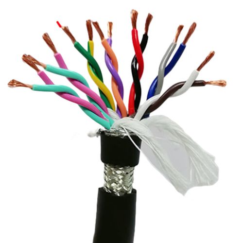
VFD Dedicated Cable (RVVP Type) is a shielded flexible multi-core control cable designed specifically for the low-voltage auxiliary circuits of variable frequency drives — the analog speed reference, digital start/stop commands, fault relay contacts, and serial communication signals that connect the VFD to the PLC, HMI, or pushbutton station that controls it.
The "RVVP" designation comes from the Chinese cable standard system:
| Letter | Meaning | Description |
|---|---|---|
| R | Flexible (软) | Class 5 fine stranded bare copper conductor — flexible for control cabinet and cable tray wiring |
| V | PVC insulation (聚氯乙烯绝缘) | PVC core insulation, 70°C temperature class |
| V | PVC sheath (聚氯乙烯护套) | PVC outer jacket for mechanical and environmental protection |
| P | Braid shield (编织屏蔽) | Tinned copper wire braid, ≥80% coverage |
This is not the cable that connects the VFD output to the motor — that is the VFD Motor Cable, a heavier 0.6/1 kV cable with multi-layer insulation designed for PWM voltage waveforms. The RVVP cable carries the control signals: the decisions that tell the drive when to run, how fast, and in which direction.
RVVP in the VFD Control Architecture — Where It Fits
In a typical VFD installation, three cable types serve three different purposes:
| Cable Type | Connects | Voltage Class | Key Requirement |
|---|---|---|---|
| VFD Motor Cable | VFD output (U/V/W) to motor | 0.6/1 kV | PWM withstand, low capacitance, symmetric ground, shield for EMC |
| RVVP VFD Control Cable | PLC/pushbutton/HMI to VFD control terminals | 300/500 V | Shield for noise immunity on analog/digital signals, flexible for cabinet wiring |
| Power Supply Cable | Mains supply to VFD input (L1/L2/L3) | 0.6/1 kV | Standard building wire or flexible power cable |
The RVVP cable occupies the control signal path — the smallest conductor cross-sections (0.12–0.50 mm² for signals) and the lowest voltage rating (300/500 V), but with the highest requirement for noise immunity because the analog speed reference signal (0–10 V DC at microamp-level current) is the most susceptible to EMI in the entire VFD installation.
VFD Control Signal Types and Their Cable Requirements
| VFD Terminal Type | Signal | Cable Core Size | Why Shield Matters |
|---|---|---|---|
| Analog Input (AI) | 0–10 V DC speed reference from PLC analog output | 0.12–0.30 mm² (low current, high impedance) | Most noise-sensitive — 100 mV of coupled noise = 1% speed error at 10 V full scale; unshielded cable can pick up several volts from adjacent motor power cables |
| Analog Input (AI) | 4–20 mA speed reference from PLC | 0.20–0.50 mm² | Less noise-sensitive than voltage mode (current loop is low impedance), but shield is still recommended where VFD power cables are in the same tray |
| Analog Output (AO) | 0–10 V or 4–20 mA feedback (speed, current, torque) to PLC | 0.20–0.50 mm² | Noise on the feedback signal creates errors in the PLC monitoring system — incorrect speed/torque readings trigger false alarms |
| Digital Input (DI) | Start, stop, forward, reverse, jog (24 V DC typically) | 0.30–0.75 mm² | 24 V DC digital inputs have good noise margin (~10 V threshold), but unshielded cable near PWM power can still cause false triggers |
| Relay Output (TA/TB/TC) | Drive fault, drive running status to PLC digital input | 0.50–1.0 mm² (contact switching current) | Least noise-sensitive of all VFD signals — dry contacts are low impedance when closed |
| RS-485 Communication | Modbus RTU data (A/B terminals) | 0.20–0.50 mm² twisted pair | RS-485 is differential and reasonably noise-tolerant, but the twisted pair plus overall shield is necessary for reliable communication at typical 9 600–115 200 baud rates |
RVVP vs Alternative VFD Control Cables
| Cable Type | Shield | Insulation | Temperature | Best For |
|---|---|---|---|---|
| RVVP | Overall tinned copper braid, ≥80% | PVC | -15°C to +70°C flexing | Indoor VFD control cabinets and cable trays; general-purpose VFD signal wiring |
| RVVP with PUR jacket | Overall braid | PVC cores, PUR jacket | -30°C to +80°C flexing | VFD control wiring on moving machine sections where oil/coolant exposure is present |
| Double-shielded signal cable | Foil per pair + overall braid | PE low-capacitance | -30°C to +80°C flexing | High-precision analog speed reference (mV-level) and high-speed serial; over-specified for standard VFD digital I/O |
| Unshielded TRVV | None | PVC | -5°C to +70°C flexing | Not recommended for any VFD signal in an industrial environment — the noise coupling risk is too high |
For the vast majority of VFD installations — a drive in a control cabinet, the motor power cable in a cable tray, and the control signals from the PLC in the same cabinet — RVVP is the correct choice: adequate shielding, proven PVC construction, economical, and widely available.
Application Analysis: Where RVVP VFD Control Cables Are Used
- PLC-to-VFD control cabinet wiring: Inside the electrical cabinet, a 12-core or 16-core RVVP cable carries all VFD control signals from the PLC terminal strip to the VFD control terminal block — analog speed reference, digital start/stop, fault relay, and RS-485 communication — in one neatly dressed cable
- Remote VFD control station: A pushbutton station or HMI panel on the machine frame or operator desk, connected to the VFD control terminals via RVVP cable — start, stop, speed potentiometer (3-wire 10 kΩ pot), and fault lamp
- Multi-drive control consolidation: On a machine with 3 or 4 VFDs, a single multi-core RVVP cable from the PLC can carry speed reference (AI1) and start/stop (DI1) for each drive — reducing the number of individual control cables in the cabinet trunking
- VFD parameter programming and monitoring: RS-485 Modbus RTU link from PLC or SCADA to multiple VFDs on a multi-drop network — RVVP with twisted pair for data (A/B) plus additional cores for the common 0 V reference
- Retrofit of legacy VFD installations: Older drives with banks of unshielded single-core control wiring — replacing with RVVP multi-core improves noise immunity and simplifies cable management in the cabinet
Why Choose Yichi for RVVP VDF Control Cables
- Manufactured to the RVVP standard with braid coverage verified: ≥80% tinned copper braid coverage, optically checked on production samples — not estimated from braid parameters. The braid is the noise barrier between the PWM power section and the control signals; we make sure it works
- Core counts matched to VFD I/O: Standard catalog includes 3-core (speed pot), 5-core (speed pot + start/stop), 8-core (full basic VFD control), 12-core and 16-core (VFD with multi-function terminals and serial communication) — so you are not paying for cores you do not need
- Junction-ready conductor sizes: The 0.12–0.20 mm² signal cores fit directly into VFD control terminal blocks (typically cage-clamp or screw, accepting 0.2–1.5 mm²). No need to crimp ferrules onto hair-thin conductors
- Cost-effective PVC construction for its intended environment: RVVP is designed for indoor control cabinets and cable trays at moderate temperatures. For outdoor, sub-zero, or oil-exposed VFD installations, we recommend the PUR-jacketed alternative and will not sell you a PVC cable for the wrong environment
- Factory-direct value on VFD signal cabling: VFD control wiring is easy to overlook in the project BOM, but a failed analog speed reference cable stops production just as surely as a failed motor power cable. Yichi RVVP cables are an economical, factory-direct investment in VFD signal reliability