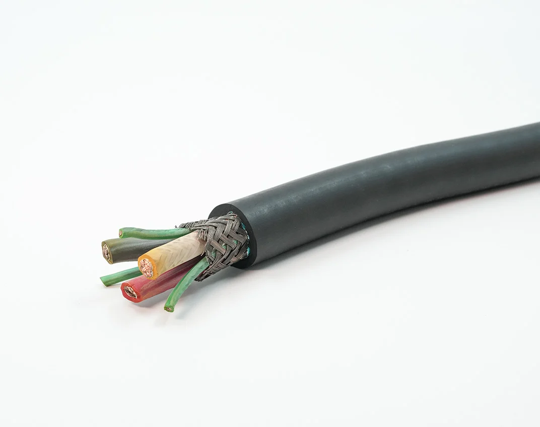
Detailed Description
What Is a VFD Motor Cable?
A VFD motor cable is the power connection between a variable frequency drive (inverter) output and the motor it controls. At first glance, it looks like any other three-phase power cable — three cores plus earth. But the electrical environment on a VFD output is fundamentally different from a mains-fed motor circuit, and a cable not designed for that environment will fail in ways that are difficult to diagnose.
A modern IGBT-based VFD synthesizes the motor voltage from a series of rectangular pulses — the PWM (Pulse Width Modulation) waveform. The key electrical characteristics that a VFD motor cable must handle are:
- High dV/dt — the voltage switches from near-zero to the full DC bus voltage (~560 V for a 400 V drive) in typically 50–200 nanoseconds. That is a dV/dt of 1 000–10 000 V/µs. A standard PVC-insulated cable sees this as a succession of voltage impulses that stress the insulation at a rate far higher than 50 Hz mains
- Reflected wave voltage doubling — the PWM pulse travels down the cable as a transmission line. At the motor terminals, the impedance mismatch reflects the pulse back toward the drive, and the reflected wave adds to the next incident pulse. For cable runs longer than roughly 15–30 metres (depending on the drive's dV/dt), the peak voltage at the motor terminals can approach twice the DC bus voltage — up to 1 120 V on a 400 V system
- Common-mode voltage and bearing currents — the PWM waveform contains a high-frequency common-mode component that capacitively couples through the motor's internal stray capacitance to the rotor shaft, creating a shaft voltage. If that voltage exceeds the breakdown voltage of the bearing lubricant film (typically 5–30 V), it discharges through the bearing — causing pitting, fluting, and premature bearing failure
VFD Motor Cable vs Standard Motor Cable — Why the Construction Differs
| Parameter | VFD Motor Cable | Standard Motor Cable (e.g. NYY, NYCY) |
|---|---|---|
| Insulation system | 3-layer (conductor shield + EPR primary + insulation shield) | 1-layer PVC or XLPE |
| dV/dt withstand | Designed for 1 000–10 000 V/µs | Designed for 50 Hz sinusoidal voltage; dV/dt ~0.15 V/µs |
| Reflected wave voltage | Insulation tested for >1 100 V peak | Insulation tested at 3 500 V AC RMS (~5 000 V peak) — passes the DC test but degrades over time under repetitive impulse stress |
| Partial discharge resistance | Semi-conductive layers ensure uniform E-field, raising PD inception voltage | No defined E-field control — partial discharge can initiate in air voids at the conductor-insulation boundary |
| Earth conductor | 3P+3PE symmetric — three PE conductors distribute earth current evenly | 3P+PE or 4P — single PE, asymmetric |
| Shield | Mandatory braid shield for EMC and common-mode current path | Optional braid or wire armour — not specified for common-mode return |
| Bearing current mitigation | Symmetric PE reduces common-mode coupling that creates shaft voltage | No specific bearing current mitigation |
The cost difference is real — the three-layer insulation system adds material and manufacturing steps. But a single motor rewind or bearing replacement often exceeds the price difference.
The Symmetric 3P+3PE Configuration — How It Reduces Bearing Currents
In a standard 3P+PE cable, the single protective earth conductor is not symmetrically positioned relative to the three power conductors. This asymmetry creates an uneven capacitive coupling from each phase to ground, generating a net common-mode current that flows in the PE conductor and, from the motor frame, through the shaft to the bearings.
In a 3P+3PE symmetric cable, each of the three PE conductors is positioned adjacent to one power conductor in a rotationally symmetric arrangement — typically the PE conductors fill the gaps between the three power cores in the cable cross-section. This symmetry:
- Equalizes the capacitive coupling from each phase to ground, reducing the net common-mode current
- Provides a low-impedance path for the high-frequency common-mode current directly from the motor frame back to the VFD, bypassing the motor shaft
- Splits the fault current path across three PE conductors, reducing the ground-potential rise at the motor during an earth fault
Cable Length Limits and Reflected Wave Voltage
| Drive DC Bus Voltage | Cable Length | Peak Voltage at Motor (Typical) | Insulation Requirement |
|---|---|---|---|
| 560 V (400 V drive) | <15 m | ~600 V | Standard PVC/XLPE 0.6/1 kV cable generally acceptable |
| 560 V (400 V drive) | 15–50 m | 700–900 V | VFD-rated cable recommended — 3-layer insulation |
| 560 V (400 V drive) | 50–150 m | 900–1 120 V | VFD-rated cable mandatory — 3-layer insulation + output reactor or dV/dt filter at drive |
| 560 V (400 V drive) | >150 m | ~1 120 V | Output sine-wave filter required at drive; even VFD-rated cable may degrade over time without filter |
| 975 V (690 V drive) | <10 m | ~1 100 V | VFD-rated cable mandatory from shortest length due to higher starting voltage |
The practical rule for 400 V drives: below 15 metres, a good-quality motor cable with a shield may be adequate. Between 15 and 50 metres, the VFD motor cable with three-layer insulation is the correct specification. Above 50 metres, add a dV/dt output filter or sine-wave filter at the drive — the cable alone should not be expected to handle the full reflected-wave voltage indefinitely.
Application Analysis: Where VFD Motor Cables Are Used
- Industrial pump and fan drives: VFD-driven centrifugal pumps, cooling tower fans, and HVAC air handlers — often with long motor cable runs (30–100 m) where reflected-wave voltage is the dominant design constraint
- Conveyor drive systems: Multiple VFD-powered drive rollers on a single conveyor line — the motor cables run in the same tray as sensor and control cables, requiring shield effectiveness for EMC compliance
- Machine tool spindle drives: High-speed spindle motors (up to 24 000 rpm) driven by VFDs with PWM switching frequencies of 8–16 kHz — the highest dV/dt and reflected-wave stress of any industrial VFD application
- Crane and hoist VFD drives: Travel, cross-travel, and hoist motors on overhead cranes — the motor cable must handle continuous flex in the festoon or cable reel system as well as the VFD electrical environment
- Marine and offshore VFD drives: Thruster motors, pump motors, and winch motors on vessels and offshore platforms — VFD motor cables with oil-resistant PUR jacket in enclosed, high-humidity environments
Why Choose Yichi for VFD Motor Cables
- Three-layer insulation manufactured from the conductor out: Conductor shield → EPR primary insulation → insulation shield — each layer extruded in a single continuous process for intimate bonding that prevents air voids at the layer interfaces (the primary cause of partial discharge in multi-layer cables)
- 3P+3PE symmetric construction as standard for this cable type: We do not offer VFD motor cable in 3P+PE — the symmetric PE configuration is a fundamental part of the cable's design for reducing common-mode current and bearing currents, not an optional add-on
- Shield that provides a genuine EMC return path: Braid coverage ≥85%, transfer impedance ≤10 mΩ/m at 10 MHz, suitable for EN 61800-3 compliance when terminated with 360° EMC glands at both the drive and motor ends
- Class 6 extra-fine stranded copper as standard: VFD motor cables often run on moving machine sections, in cable carriers, or on cable reels — Class 6 stranding ensures the conductors survive the mechanical duty
- Application support for drive-cable matching: We help assess the cable length, drive switching frequency, and motor insulation class for your specific VFD installation and recommend the correct cable specification — including whether an output filter is needed at the drive