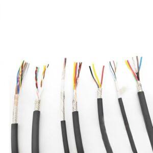
Linear Motor Cable — High-Power Combined Servo Flex Cable with Integrated Hall Sensor and Thermal Feedback for Long-Travel Direct-Drive Axes
Robot & Automation Cables /Linear Motor Series

Linear Motor Cable — High-Power Combined Servo Flex Cable with Integrated Hall Sensor and Thermal Feedback for Long-Travel Direct-Drive Axes

Linear motor cable integrating power phases (U/V/W/PE) + Hall effect sensor + temperature sensor + limit switch in a single flexible sheath. IEC 60228 Class 6 ultra-fine copper, 600/1000 V power rated, 300/500 V signal rated. PUR jacket, 85%+ tinned copper braid overall shield. Long-travel optimized: up to 50 m stroke, 5 m/s travel, 50 m/s² acceleration. Low-capacitance PP/PE signal insulation. For iron-core and ironless linear motors in semiconductor, machine tool, and precision automation.

Key Features

All-in-one linear motor cable: power (3 phases + PE) + Hall sensors (5–8 signals) + thermal sensor (2 signals)
600/1 000 V power cores + 300/500 V signal cores — voltage class separation with PET fleece inter-layer isolation
IEC 60228 Class 6 ultra-fine copper with short-lay stranding — 10+ million flex cycles at 7.5×D
Long-travel rated: up to 50 m stroke, 5 m/s travel speed, 50 m/s² acceleration
Low-capacitance PP/PE signal insulation — clean Hall sensor signals without crosstalk from PWM power phases
Tinned copper braid shield (85%+) with PET inner wrap — EMI protection for both power and signal conductors
PUR jacket, Shore 85–90 A — oil, coolant, UV, and hydrolysis resistant; halogen-free
Kevlar tensile fillers for long-travel carrier stability — prevents cable sag and internal stress

Applications

Iron-core linear motors — high-force axes in CNC machine tools and large-format machiningIronless (U-channel) linear motors — precision semiconductor wafer stages and inspection systemsLinear motor gantry systems — dual-motor synchronized axes in pick-and-place and assemblyDirect-drive precision stages — linear encoder + Hall sensor feedback cable in motionHigh-speed linear transport — magnetic levitation and linear motor propulsion systemsFlat and tubular linear motors — general-purpose direct-drive linear motion applications

Technical Specifications

Power Conductor Bare copper, IEC 60228 Class 6; 1.5–16 mm² (standard), up to 35 mm² on request
Power Core Insulation PP — low capacitance, high dielectric strength for 600/1 000 V class
Power Core Colors U: Black, V: Red, W: Blue, PE: Green-Yellow
Signal Conductor (Hall) Bare copper, IEC 60228 Class 6; 0.25–0.50 mm²
Signal Conductor (Thermal) Bare copper, IEC 60228 Class 6; 0.25–0.50 mm²
Signal Insulation PP or PE — low capacitance, stable dielectric
Signal Core Colors Color coded per linear motor manufacturer standard or custom
Core Stranding Power cores in center + signal cores in outer layer — PET fleece separation
Tensile Fillers Kevlar (aramid) in core center and between layers
Inner Wrap PET fleece — separates core assembly from shield
Shield Tinned copper braid, ≥85% coverage — overall shield over power + signal
Outer Jacket PUR, Shore 85–90 A, halogen-free — oil, coolant, UV, and hydrolysis resistant
Jacket Color Black RAL 9005, Orange RAL 2003
Rated Voltage (Power) 600/1 000 V
Rated Voltage (Signal) 300/500 V
Test Voltage (Power) 3 500 V AC / 5 min (core-core; core-shield)
Test Voltage (Signal) 2 000 V AC / 5 min (core-core)
Insulation Resistance ≥20 MΩ × km (at 20°C)
Capacitance (Signal to Shield) < 100 pF/m per signal core
Temperature Range (Moving) -30°C to +80°C
Temperature Range (Fixed) -40°C to +90°C
Minimum Bend Radius (Moving) 7.5 × outer diameter (10× for long-travel >20 m)
Minimum Bend Radius (Fixed) 5 × outer diameter
Maximum Travel Speed 5 m/s (gliding); 3 m/s (suspended)
Maximum Acceleration 50 m/s²
Maximum Travel Distance 50 m (standard); >50 m with enhanced tensile reinforcement
Flex Life 10 million cycles (standard); 15 million (enhanced with Class 6+ conductor)
Common Configurations 4G2.5 + 8×0.5 · 4G4 + 6×0.5 + 2×0.5 · 4G6 + 8×0.5 + 2×0.5 · 4G10 + 10×0.5 + 2×0.5
Flame Retardant IEC 60332-1-2; UL VW-1
Oil Resistance IEC 60811-404
UV Resistance DIN EN ISO 4892-2
Halogen-Free IEC 60754-1
Certifications CE, RoHS, REACH

Detailed Description

Linear Motors Need a Different Cable

A rotary servo motor is bolted to a fixed frame. The cable connects a stationary cabinet to a motor that does not move. All the motion is internal to the motor — the cable is fixed.

A linear motor is fundamentally different: the cable connects a stationary cabinet to a motor that is the moving element — the forcer/slider travels along the entire length of the axis. The cable must:

  • Travel with the motor through the full stroke (1–10+ meters)
  • Carry both high-power motor phase current and precision Hall sensor feedback signals in the same sheath
  • Maintain signal integrity despite the PWM power conductors being millimeters from the signal conductors
  • Survive millions of high-speed, long-travel cycles in a cable carrier
A standard servo motor cable handles power only — Hall sensors and thermal protection require a separate signal cable. A standard control cable handles signals only — it cannot carry 600/1 000 V motor power. The linear motor cable does both.

The Hall Sensor Challenge — Clean Signals Next to Noisy Power

Hall effect sensors detect the linear motor's magnetic pole position — they are the "encoder" equivalent for linear motors. These sensors output low-level analog or digital signals (typically 5 V or 24 V) that tell the servo drive exactly where the forcer is along the magnet track.

The problem: the power conductors carrying the motor phase current (switching at 4–16 kHz with 5 kV/μs dv/dt) are inside the same cable as the Hall sensor signal conductors, separated by only a few millimeters of insulation.

Without proper design, the PWM power waveform capacitively couples into the Hall sensor signals, corrupting the position feedback. The servo drive loses commutation — the motor loses position or faults.

Three design features prevent this:

1. Physical Separation — PET Fleece Inter-Layer

The power conductors are stranded in the cable's inner core. The signal conductors are in a separate outer layer. A PET fleece tape between the layers provides additional dielectric isolation beyond the individual core insulation.

2. Low-Capacitance Signal Insulation

The Hall sensor cores use PP or PE insulation — materials with low dielectric constants (εr ≈ 2.3) vs PVC (εr ≈ 4.5). Lower dielectric constant = lower capacitance between power and signal cores = lower coupled noise voltage.

3. Overall Shield — Tinned Copper Braid

The 85%+ coverage braid shield surrounds the entire cable assembly — both power and signal cores. The shield intercepts radiated EMI from external sources AND provides a ground reference plane that reduces capacitive coupling between the power and signal conductors inside the cable.

Typical Configurations by Motor Size

Linear Motor TypeTypical PowerHall SensorsThermalTypical Configuration
Small ironless (< 200 N)1.5–2.5 mm²5 signals (3 Hall + 2 power)2 signals (PTC/KTY)4G1.5 + 7 × 0.5
Medium ironless (200–500 N)2.5–4 mm²5 signals2 signals4G2.5 + 7 × 0.5
Iron-core (500–2 000 N)4–10 mm²5–8 signals2 signals4G4 + 8 × 0.5 + 2 × 0.5
Large iron-core (> 2 000 N)10–35 mm²8 signals2 signals4G10 + 8 × 0.5 + 2 × 0.5
G = with green-yellow protective conductor. Hall sensor signal count varies by motor manufacturer — contact our engineering team with your motor datasheet for the exact configuration.

Long-Travel Design — Beyond Standard Carriers

Standard drag chain cable is designed for travels up to 10–20 m. Linear motor axes often exceed this — semiconductor wafer stages routinely travel 2–5 m at nanometer precision, and large-format machine tools can have 10–30 m strokes.

Long-travel design considerations:

  • Tensile load at the carrier take-off point: A 10 m carrier filled with cable weighs 5–15 kg. At the moving end, the entire weight of the cable in the carrier pulls on the clamp point. Kevlar tensile fillers carry this load — not the copper conductors
  • Cable sag in the carrier: Long horizontal carriers experience cable sag between support points. The sag creates non-uniform bend stress. Higher tensile reinforcement and optimized carrier support spacing address this
  • Heat buildup in long carriers: Friction over long travels generates heat that cannot dissipate easily from the middle of the carrier. PUR jacket is specified partly for thermal stability — it maintains mechanical properties at elevated temperature better than PVC

Why Choose Yichi Cable Linear Motor?

  • Motor-specific configuration: Send us your linear motor manufacturer and model. We match the Hall sensor pinout, thermal sensor type (PTC, KTY, PT100), and power cross-section to your motor datasheet — not a generic "one-size-fits-many" cable
  • Hall sensor signal integrity tested: Every production batch is tested for power-to-signal crosstalk at the motor's PWM switching frequency — we verify that the Hall sensor signals remain clean at full motor power
  • PET fleece inter-layer as standard: The power-to-signal isolation layer is standard on every linear motor cable — not an extra-cost option
  • Pre-assembled with connectors: Motor-specific connectors (M23, M40, M58 power + M17, M23 signal) pre-assembled and tested — plug and commission, no field wiring

Product Inquiry

Product: Linear Motor Cable — High-Power Combined Servo Flex Cable with Integrated Hall Sensor and Thermal Feedback for Long-Travel Direct-Drive Axes

Add technical specifications (optional)

The more detail you provide, the faster and more accurate our quotation.

No file chosen

PDF, Office, image or CAD file — up to 5 MB

Need Help?

Certifications

ISO 9001
Quality
CE
European
RoHS
Environmental
TÜV
Certification

Need a Quote for This Product?

Send us your requirements and receive a detailed quotation within 24 hours.