Detailed Description
What Makes the High-Flex Servo Motor Power Cable with Brake Conductors the Right Fit for Servo Drive Wiring
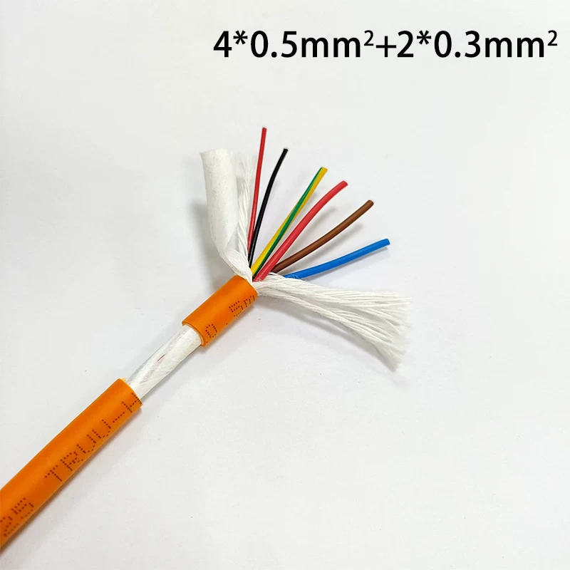
A servo motor needs two things: power conductors to feed the motor windings, and control conductors to release and engage the holding brake. Running them separately means two cables occupying the drag chain, two pulling tensions to manage, and two connection points that can fail. This cable puts both in one jacket — four power cores plus two brake cores — so one pull completes both functions.
The brake cores are simple DC control circuits sized at 0.3 mm² or 0.75 mm². They are not differential signal pairs and do not require impedance control. That distinction matters: if your application needs encoder feedback, a composite power-plus-feedback cable is the correct choice. If your servo motor has a holding brake and you want to cut the number of cables in your drag chain, this is the cable for the job.
Layer-by-Layer Construction
From the inside out, the cable is built as follows:
- Conductor — multi-strand fine-stranded tinned annealed copper. The tin coating resists oxidation and keeps the strand surface solderable.
- Insulation — flexible PVC extruded over each core.
- Filler — tensile cotton rope and non-woven fabric run through the core assembly. The cotton rope absorbs pulling force; the non-woven fabric allows cores to slide against each other during repeated bending instead of rubbing.
- Shield (shielded version only) — tinned copper braid applied over the cabled cores to suppress interference from VFD and servo drive switching.
- Jacket — drag-chain-rated flexible jacket compound over the complete assembly.
Key Specifications and Dimensions
The tables below list finished outer diameters by core count and cross-section.
Unshielded Type (4-Core)
| Size | Finished Outer Diameter |
|---|---|
| 4 × 0.2 mm² | 4.5 mm |
| 4 × 0.3 mm² | 4.8 mm |
| 4 × 0.5 mm² | 6.8 mm |
| 4 × 0.75 mm² | 7.2 mm |
| 4 × 1.0 mm² | 7.8 mm |
| 4 × 1.5 mm² | 8.9 mm |
| 4 × 2.5 mm² | 11.0 mm |
| 4 × 4.0 mm² | 13.2 mm |
| 4 × 6.0 mm² | 14.4 mm |
4-Core Power + 2-Core Brake Combination
| Size | Finished Outer Diameter |
|---|---|
| 4 × 0.5 + 2 × 0.3 mm² | 7.4 mm |
| 4 × 0.75 + 2 × 0.3 mm² | 8.0 mm |
| 4 × 0.75 + 2 × 0.75 mm² | 9.4 mm |
| 4 × 1.5 + 2 × 0.75 mm² | 11.2 mm |
| 4 × 2.5 + 2 × 0.75 mm² | 12.8 mm |
Shielded Type (TRVVP)
| Size | Finished Outer Diameter |
|---|---|
| 4 × 0.2 mm² | 4.9 mm |
| 4 × 0.3 mm² | 5.2 mm |
The recommended combinations with brake cores are 4 × 0.5 mm² + 2 × 0.3 mm², 4 × 0.75 mm² + 2 × 0.3 mm², and 4 × 1.5 mm² + 2 × 0.75 mm², each available in unshielded or shielded versions. The shielded (TRVVP) type is listed for 4 × 0.2 mm² and 4 × 0.3 mm²; other core counts can be produced on request.
Flex Performance and Drag Chain Suitability
This cable is rated for 15 million flex cycles. That figure comes from continuous reciprocating motion in drag chain applications, not occasional movement. The tensile cotton rope and non-woven fabric filling play a direct role here: the cotton rope takes up pulling force as the cable moves through the chain, and the non-woven fabric keeps cores sliding past each other rather than wearing against each other each time the cable bends.
The drag-chain-rated jacket compound resists oil contamination and abrasion under continuous motion. For environments where VFD or servo drive noise is present, the tinned copper braid shield reduces interference coupled onto the brake control circuit.
Where Servo Motor Power and Brake Cables Are Used
- Automated assembly lines — servo motors at each station need power and brake wiring, and drag chain space is limited. One cable replaces two.
- CNC machining centers — X, Y, and Z axis servo motors each require power and brake connections. An integrated cable cuts the cable count in the drag chain.
- Injection molding machines — multiple servo drives distributed around the machine; reducing cable count simplifies routing and lowers the number of failure points.
- Robotic arms — joints bend continuously and the cable carrier space is tight. High flex life and integrated brake wiring both help.
- Packaging equipment — servo motors inside compact enclosures benefit from reduced wiring volume.
- Machine tool retrofits — adding brake functionality to existing servo motors often means running one new cable instead of two.
Selection and Installation Notes
Voltage rating and temperature range are supplied to customer-specified requirements. Provide these parameters as part of your inquiry.
Minimum bending radius depends on your installation and on the drag chain manufacturer's requirements. Confirm it for your specific routing before installation.
For shielded versions, terminate the braid at both cable ends to ground for effective interference suppression.
Before installation, check the finished outer diameter against your drag chain inner dimensions. The sizes in the tables above help you assess fit in your existing chain.
Available Configurations and How to Inquire
Configurations available include:
- Core count: standard 4-core and 4+2 core; other configurations available on request
- Cross-section: 0.2 mm² to 6.0 mm² (4-core); brake cores at 0.3 mm² or 0.75 mm²
- Shielding: unshielded or tinned copper braid shield
- Jacket color: orange
- Lengths: available on request