Detailed Description
Why Flat Cable on a Bridge Crane?
Bridge cranes move on two axes: the bridge travels along the runway (long-travel), and the trolley traverses across the bridge girder (cross-travel). Both motions require flexible power and control cables that travel with the moving component. There are two ways to manage these traveling cables:
Round Cable on a Motorized Drum
The traditional approach. A round cable is wound onto a spring-loaded or motorized cable drum. As the trolley or bridge moves, the drum pays out or takes up cable. This works reliably, but it has drawbacks on bridge cranes:
- The drum and its mounting structure consume vertical and horizontal space on the crane bridge — space that could be used for a larger hoist, wider trolley, or additional auxiliary equipment
- A motorized drum adds another electromechanical component to maintain — motor, gearbox, slip rings, limit switches
- On long bridge spans (20–40 meters), the drum must store 40–80 meters of round cable — a large, heavy assembly
Flat Cable on a Festoon System
The modern alternative. A flat cable is suspended in loops from cable trolleys that ride on a C-rail or I-beam track. As the trolley or bridge moves, the loops open and close. Key advantages:
- No drum needed: The flat cable hangs in self-supporting loops — no motor, no gearbox, no slip rings
- Flat profile stacks compactly: When the loops close, the flat cable stacks neatly — the total stack height is much less than an equivalent round cable coil on a drum
- Both power and control in one cable: A single flat cable can carry power conductors for the hoist motor alongside control conductors for limit switches and pendant signals — fewer festoon loops, fewer cable trolleys
- Easy to add or replace: Adding a conductor to a flat cable assembly means changing one cable; modifying a round cable requires a complete custom cable design
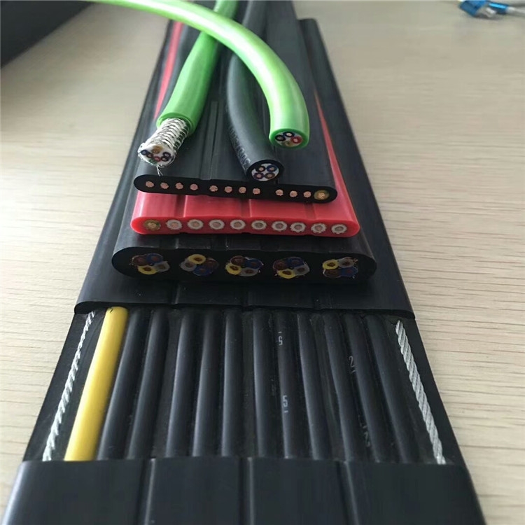
Steel Wire Edge Reinforcement — Protecting the Geometry
A flat cable's defining characteristic is its flatness. If the cable twists, corkscrews, or deforms under its own weight in the festoon loop, it will not track properly through the cable trolleys — it will jam, wear prematurely, or pull out of the trolley saddles.
The two galvanized steel wire ropes embedded in the longitudinal edges solve this in three ways:
1. Anti-Twist
The parallel steel wires provide longitudinal stiffness that resists torsional deformation. When the festoon loop opens or closes, the cable bends in one plane (flat-wise) but is prevented from twisting (edge-wise) by the edge wires.
2. Tensile Load Distribution
In a long festoon loop, the cable supports its own weight plus wind load (for outdoor cranes). The steel wires carry this tension, preventing the copper conductors from elongating under sustained load.
3. Wear Surface
The trolley saddles grip the cable primarily on the flat faces, but edge contact occurs during loop transition. The steel wires at the edges provide a sacrificial wear surface — they erode before the copper conductors are exposed.
Conductor Layout — Designing the Flat Cable Cross-Section
A flat cable is not simply a round cable that has been squashed. The conductor layout is deliberately designed, with each type of conductor occupying a specific position across the cable width:
| Position (Left to Right) | Conductor Type | ID | Function |
|---|---|---|---|
| Edge | Steel Wire (L) | — | Tensile reinforcement, anti-twist, sacrificial wear surface |
| Position 1 | Power | PE | Equipment ground (green/yellow) |
| Position 2 | Power | P1 | Phase 1 — hoist motor |
| Position 3 | Power | P2 | Phase 2 — hoist motor |
| Position 4 | Control | C1 | Hoist limit switch up |
| Position 5 | Control | C2 | Hoist limit switch down |
| Position 6 | Control | C3 | Trolley limit switch left |
| Position 7 | Control | C4 | Trolley limit switch right |
| Position 8 | Control | C5 | E-stop circuit |
| Position 9 | Signal | S1 | Spare / auxiliary |
| Position 10 | Signal | S2 | Spare / auxiliary |
| Edge | Steel Wire (R) | — | Tensile reinforcement, anti-twist, sacrificial wear surface |
Yichi Flat Cable Manufacturing
- Parallel lay-up with controlled pitch: Conductors are laid in parallel on a precision guide table before jacket extrusion. Pitch between adjacent conductors is controlled to ±0.3 mm — inconsistent pitch causes irregular bending stiffness across the cable width
- Steel wires pre-tensioned: The edge wires are fed into the extrusion line under controlled tension — this prevents the wires from kinking or shifting during jacket cooling, which would create localized stiff spots
- Jacket thickness profiled: The flat cable jacket is not uniform thickness — the flat faces are slightly thicker than the edges because the faces bear the trolley saddle contact. Our extrusion die is profiled accordingly
- Print marking on jacket face: Cable identification (type, core count, cross-section, voltage rating) is printed on one flat face at 500 mm intervals — readable without removing the cable from the trolley saddles