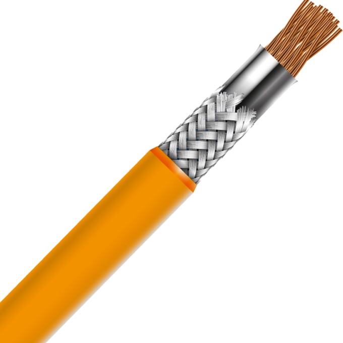
EV Charging Station Cable — IEC 60502-1 XLPE Insulated SWA Armoured 0.6/1 kV Power Supply Cable for AC and DC Electric Vehicle Charging Stations, from Distribution Board to Charger, Single-Phase and Three-Phase, Outdoor and Indoor Fixed Installation
EV Charging & Renewable Energy Cables /EV Charging Station Power Supply

EV Charging Station Cable — IEC 60502-1 XLPE Insulated SWA Armoured 0.6/1 kV Power Supply Cable for AC and DC Electric Vehicle Charging Stations, from Distribution Board to Charger, Single-Phase and Three-Phase, Outdoor and Indoor Fixed Installation

EV charging station cable: IEC 60502-1 XLPE insulated, SWA armoured, 0.6/1 kV power supply cable for connecting EV chargers to the distribution board. Single-phase (3-core) and three-phase (5-core). 6–50 mm² copper. For AC wallbox, DC fast charger station power feed. PE sheath, outdoor UV-resistant. CE, RoHS.

Key Features

IEC 60502-1 compliant power cable specifically selected and sized for EV charging station power supply — the cable that connects the building distribution board to the AC wallbox or DC fast charger; rated 0.6/1 kV for the standard low voltage supply voltage to EV chargers
Three-phase 5-core (3P+N+PE) for AC charging stations — 6 mm², 10 mm², or 16 mm² copper for 11 kW to 22 kW three-phase AC chargers; the dedicated PE conductor ensures the charger's earth reference is continuous from the distribution board to the charger, independent of the armour earth path
Single-phase 3-core (L+N+PE) for residential wallboxes — 6 mm² or 10 mm² copper for 3.7 kW to 7.4 kW single-phase AC home chargers; the cable is sized for continuous full-load charging with the voltage drop limited to <3% per BS 7671 / IEC 60364 requirements
SWA (steel wire armour) for mechanical protection — the armoured construction is the standard for outdoor power supply cables in the UK, Europe, and many international markets; the SWA provides mechanical protection during installation and against accidental damage, rodent attack, and garden tools in residential installations
XLPE (cross-linked polyethylene) insulation rated 90°C — the cable is sized for continuous full-load operation at the charger's rated current for the full charging session duration (up to 8–12 hours for a full charge); XLPE's 90°C rating provides the thermal margin for continuous high-current duty
PE (polyethylene) or PVC outer sheath for outdoor installation — PE sheath for direct burial of the supply cable from the house distribution board to a detached garage or outdoor charging post; PVC sheath for surface-mounted and indoor cable tray installations
Conductor cross-sections from 6 mm² to 50 mm² — covering the full range of AC and low-power DC charging station supply circuits; 6 mm² for 7.4 kW single-phase (32 A); 10 mm² for 11 kW to 22 kW three-phase; 16–50 mm² for larger charging hubs with multiple chargers or DC fast chargers
Voltage drop optimized — the cable cross-section is selected to maintain voltage at the charger terminals within the permissible range (±10% of nominal) per IEC 61851-1, ensuring the charger's power electronics and the vehicle's onboard charger operate within their rated input voltage range

Applications

Residential AC wallbox power supply — 3-core 6 mm² or 10 mm² SWA cable from the consumer unit to a 7.4 kW single-phase home EV charger mounted on an external wall or in a detached garage; the most common residential EV charger installationCommercial AC charging station power supply — 5-core 10 mm² or 16 mm² SWA cable from the distribution board to 22 kW three-phase workplace, retail, and public car park AC charging stations; typically installed in cable tray or buried ductDC fast charger station power supply — 4-core or 5-core 25–50 mm² SWA cable (or larger per charger specification) from the LV distribution board to the DC fast charger power cabinet; the power supply cable must be sized for the charger's maximum AC input current which can be 63 A to 250 A depending on the DC charger power rating (25 kW to 150 kW+)Charging hub and multi-charger installations — feeder cable from the main LV switchboard to a charging hub sub-distribution board feeding multiple chargers; typically 4-core or 5-core 35–95 mm² SWA cable for aggregated loadDetached garage and outbuilding charger supply — SWA cable for buried installation from the house consumer unit to a detached garage or carport where the EV charger is installed; the armoured construction is required for buried cable protectionSolar carport EV charging — power supply cable for EV chargers integrated into solar carport structures; the cable may be routed overhead in the carport steelwork or underground from the building to the carportStreet lighting column EV charger — retrofitting EV charging points into existing street lighting columns; a new SWA power supply cable may be required from the street lighting feeder pillar to the charging point in the column

Technical Specifications

Standard IEC 60502-1: Power cables with extruded insulation and their accessories for rated voltages from 1 kV (Um = 1.2 kV) up to 30 kV; also compliant with BS 5467 (UK standard for armoured power cables commonly specified for EV charger installations)
Rated Voltage (U₀/U) 0.6/1 kV (Um = 1.2 kV)
Conductor Material Bare copper; IEC 60228 Class 2 stranded; for the continuous high-current duty of EV charger supply circuits, copper conductor is standard — aluminum is not typically used due to the higher cross-section required for equivalent ampacity and the bi-metallic termination complexity at the charger terminals
Conductor Cross-Sections — Single-Phase (3-Core) 6 mm² (32 A, 7.4 kW); 10 mm² (40 A with derating margin); 16 mm² (63 A with derating)
Conductor Cross-Sections — Three-Phase (5-Core) 6 mm² (32 A, 22 kW); 10 mm² (40 A with margin); 16 mm² (63 A with margin); 25 mm² (80 A); 35 mm² (100 A); 50 mm² (125 A)
Core Configuration — Single-Phase EV Charger 3-core: L (brown) + N (blue) + PE (green-yellow)
Core Configuration — Three-Phase EV Charger 5-core: L1 (brown) + L2 (black) + L3 (grey) + N (blue) + PE (green-yellow)
Core Insulation — XLPE Cross-linked polyethylene; rated 90°C continuous; 250°C short-circuit; the standard insulation for EV charger power supply cables because the continuous duty at the charger's rated current can approach the 70°C limit of PVC insulation when the ambient temperature in the cable route is elevated
Insulation Thickness Per IEC 60502-1 Table 3; 1.0 mm (6–10 mm²); 1.0 mm (16 mm²); 1.2 mm (25–35 mm²); 1.4 mm (50 mm²)
Core Assembly (Multi-Core) Concentric stranding with non-hygroscopic filler elements
Inner Covering / Bedding Extruded PVC ST2 or PE ST7; provides the cylindrical bedding surface for the armour wires
Armour — SWA Galvanized steel wire armour per IEC 60502-1 Table 5; wire diameter 0.9 mm (6 mm² 3-core) to 2.5 mm (50 mm² 5-core); the armour serves as mechanical protection and supplementary earth fault return path
Outer Sheath — PVC ST2 Extruded PVC; black; UV-stabilized; standard for surface-mounted and indoor cable tray installation
Outer Sheath — PE ST7 Extruded PE; black; enhanced UV and moisture resistance; specified for direct burial of EV charger supply cables between buildings, to detached garages, and to outdoor charging posts
Sheath Thickness Per IEC 60502-1 Table 7; from 1.4 mm to 2.4 mm depending on the diameter over armour
Maximum DC Conductor Resistance at 20°C — Copper Per IEC 60228 Class 2; 3.08 Ω/km (6 mm²); 1.83 Ω/km (10 mm²); 1.15 Ω/km (16 mm²); 0.727 Ω/km (25 mm²); 0.524 Ω/km (35 mm²); 0.387 Ω/km (50 mm²)
Insulation Resistance at 20°C — XLPE ≥1 000 MΩ·km (core-to-core and core-to-earth at 500 V DC, 1 min)
Test Voltage (AC — Routine) 3 500 V AC / 5 min; per IEC 60502-1
Temperature Range — Continuous (Conductor) 90°C (XLPE); sheath surface: PVC 70°C max, PE 80°C max
Short-Circuit Temperature — XLPE 250°C (max 5 s) per IEC 60949
Minimum Bending Radius 12× cable OD (multi-core unarmoured); 15× cable OD (multi-core SWA armoured)
Maximum Pulling Tension 50 N/mm² of total copper conductor cross-section; use cable stocking over outer sheath
Current Rating (Typical, Copper/XLPE, 3-Core SWA, Clipped Direct, 30°C Ambient) Per IEC 60364-5-52 / BS 7671 Table 4D4A; 6 mm² = 53 A; 10 mm² = 72 A; 16 mm² = 95 A (single-phase reference); de-rate per installation method (in conduit, in thermal insulation, grouping)
Current Rating (Typical, Copper/XLPE, 5-Core SWA, Clipped Direct, 30°C) Per IEC 60364-5-52; 6 mm² = 46 A; 10 mm² = 63 A; 16 mm² = 83 A; 25 mm² = 109 A; 35 mm² = 133 A; 50 mm² = 160 A (three-phase reference)
Voltage Drop — 3-Core, 230 V Single-Phase (Typical, Copper/XLPE, mV/A/m) 6 mm² = 7.3 mV/A/m; 10 mm² = 4.4 mV/A/m; 16 mm² = 2.8 mV/A/m; for a 32 A charger on a 20 m 6 mm² cable: voltage drop = 7.3 × 32 × 20 / 1 000 = 4.7 V = 2.0% — within the <3% recommendation
Voltage Drop — 5-Core, 400 V Three-Phase (Typical, Copper/XLPE, mV/A/m) 6 mm² = 6.4 mV/A/m; 10 mm² = 3.8 mV/A/m; 16 mm² = 2.4 mV/A/m; for a 32 A 3-phase charger on a 30 m 10 mm² cable: voltage drop = 3.8 × 32 × 30 / 1 000 = 3.6 V = 0.9% — well within the limit
Cable Length — Practical Maximum (32 A, <3% VD, Single-Phase) 6 mm²: 28 m; 10 mm²: 47 m; 16 mm²: 78 m; the voltage drop limit, not the current rating, determines the maximum cable length for EV charger supply circuits
Flame Retardant — PVC Sheath IEC 60332-1-2
Flame Retardant — PE Sheath PE is not inherently flame-retardant; for building entry sections, use a PVC-sheathed section or metal conduit for the transition from buried to indoor installation
Earthing — TN-S / TN-C-S Systems The SWA armour provides a supplementary earth fault return path in parallel with the dedicated PE conductor. For TN-C-S (PME) earthing, the EV charger earthing arrangement must be per the local wiring regulations — in the UK, BS 7671 Section 722 may require a TT earth electrode for the charger rather than using the PME earth from the supply, due to the risk of an open PEN conductor creating a dangerous potential on the vehicle body
Certifications CE, RoHS; BASEC (UK), KEMA KEUR, VDE on request per national market; BS 5467 compliant construction for the UK market

Detailed Description

What Is an EV Charging Station Cable?

An EV charging station cable is the fixed-installation power supply cable that connects the building's electrical distribution system to the EV charging station — the cable that an electrician installs between the consumer unit or distribution board and the wallbox or charging post. It is not the flexible cable that plugs into the car (that is the EV charging cable — Mode 2/Mode 3). The charging station cable is a standard IEC 60502-1 low voltage power cable, selected and sized specifically for the continuous high-current duty that EV charging imposes.

The distinction matters because these two cables serve completely different functions and are specified under completely different standards:

ParameterEV Charging Station Cable (This Page)EV Charging Cable (Mode 2/3)
FunctionFixed power supply from distribution board to chargerFlexible connection from charger to vehicle
StandardIEC 60502-1 (power cable)EN 50620 / IEC 62893 (charging cable)
InstallationFixed — buried, surface-mounted, in cable trayPortable — plugged/unplugged daily
ConductorsPower only (L, N, PE ± additional phases)Power + Control Pilot + Proximity Pilot
ConstructionSolid/stranded conductor, armoured, PE/PVC sheathFlexible conductor, TPE/PUR jacket
ConnectorTerminated at charger terminals (screw/lug)Terminated at vehicle connector (Type 1/Type 2)
Flex lifeNone (fixed installation)>10 000 plug/unplug cycles, >50 000 bend cycles

Cable Sizing for EV Chargers — Continuous Duty at Full Load

The critical difference between sizing a cable for an EV charger and sizing for a typical building circuit is that the EV charger operates at its full rated current for extended periods — potentially 8–12 hours for a full vehicle charge. This is not a motor circuit that runs at full load for minutes and then drops to a lower running current, or a socket circuit where the diversity factor assumes that not all sockets are loaded simultaneously. The EV charger draws its rated current continuously for the duration of the charge session.

This imposes two sizing requirements:

  1. Thermal: The cable's continuous current rating (after de-rating for installation method, ambient temperature, and grouping) must equal or exceed the charger's rated current × 1.0 (no diversity factor applied). A 32 A charger requires a cable rated ≥32 A, not 32 A × 0.7 (the typical circuit diversity factor for a socket circuit)
  2. Voltage drop: The voltage at the charger terminals during full-load charging must be within the charger's rated input voltage range (typically ±10% of nominal, per IEC 61851-1). If the voltage drops too low, the charger may reduce charging current or shut down. IEC 60364 recommends a maximum voltage drop of 3% for the final circuit from the distribution board to the load — for a 32 A charger on a 230 V supply, this is 6.9 V maximum drop
Practical sizing example — 7.4 kW single-phase home charger:
  • Charger rating: 32 A, 230 V, single-phase
  • Cable route length: 15 m from consumer unit to external wallbox
  • Cable: 3-core XLPE/SWA/PVC, clipped direct (installation method C)
  • 6 mm² copper: 53 A rating (thermal — well above 32 A requirement); voltage drop = 7.3 mV/A/m × 32 A × 15 m / 1 000 = 3.5 V = 1.5% — acceptable
  • 10 mm² copper: 72 A rating; voltage drop = 1.3% — more margin, but larger cable is harder to terminate in the wallbox
  • Recommendation: 6 mm² is the correct specification for this installation
For a 20 m or longer run, 10 mm² may be required to keep the voltage drop within the 3% recommendation. The voltage drop, not the current rating, is typically the limiting factor for EV charger supply cable sizing.

Earthing for EV Chargers — The PEN Conductor Issue

In the UK, BS 7671 Section 722 includes specific earthing requirements for EV charging installations that affect cable selection. In a TN-C-S (PME — Protective Multiple Earthing) supply, the neutral and earth are combined into a single PEN conductor from the supply transformer to the service head, where they are separated into N and PE. If this PEN conductor breaks anywhere in the supply network (e.g., a corroded joint in the street cable), the installation's "earth" can rise to the phase voltage through connected loads — creating a dangerous potential between the earthed vehicle body and the surrounding ground.

For EV charging, this is a particular risk because a person standing on the ground touching the vehicle body would receive a shock. To mitigate this risk, BS 7671 Section 722 requires that:

  • An EV charger installed on a PME supply must use a TT earth electrode (local earth rod) OR
  • The charger must include an open-PEN detection device that disconnects the supply if the PEN voltage rises above 70 V
If the earthing arrangement is TT, the cable's armour and PE conductor are connected to the local earth electrode at the charger, not to the supply PEN-derived earth. This changes the earth fault loop impedance and the required protective device characteristics. The cable specification itself does not change — it is the earthing arrangement at the charger end that differs.

Why Choose Yichi EV Charging Station Cables

  • IEC 60502-1 XLPE insulated, correctly sized for EV charger duty: XLPE insulation at 90°C for continuous high-current charging; the thermal margin above PVC's 70°C rating provides confidence that the cable will not overheat during overnight full-load charging
  • SWA armoured as standard for EV charger supply installations: The armoured construction is the default specification for outdoor EV charger power supply cables across the UK, Europe, and many international markets. The armour provides mechanical protection during installation and throughout the charger's operating life — protection against accidental damage from gardening, DIY, and general outdoor activity around the charging location
  • Sizing support for voltage drop compliance: The voltage drop, not the thermal rating, is the critical sizing constraint for EV charger cables. Provide the charger rating, cable run length, and installation method — our application engineering team calculates the voltage drop per IEC 60364 and recommends the minimum conductor cross-section that meets both the thermal and voltage drop requirements
  • PE or PVC sheath — select for the installation environment: PE sheath for direct burial to a detached garage or outdoor charging post; PVC sheath for surface mounting on external walls and indoor cable tray routing
  • BASEC / BS 5467 compliance available for the UK market: For UK EV charger installations, the cable can be manufactured with BASEC certification and BS 5467 compliant construction — the combination of standards that UK electrical contractors and EV charger installers specify
  • Custom reel lengths for EV charger installation projects: Standard 50 m and 100 m drums for single residential installations; custom lengths for commercial and fleet charging hub projects with multiple chargers

Frequently Asked Questions

Why is the supply cable to a charger specified differently from ordinary power cable?

Because the load is continuous at full rating. The cable is sized on sustained current rather than a diversity assumption, with XLPE insulation rated 90°C continuous, which is what allows a 6 mm² three-phase core to serve a 22 kW charger.

When should I use the PE sheath instead of PVC?

PE (ST7) is specified for direct burial, where enhanced UV and moisture resistance is required. PVC (ST2) is the standard choice for surface-mounted and indoor cable tray installation.

What cross-sections cover my charger?

Single-phase 3-core: 6 mm² for 32 A / 7.4 kW, 10 mm² for 40 A with derating margin, 16 mm² for 63 A. Three-phase 5-core: 6 mm² for 32 A / 22 kW, 10 mm² for 40 A, 16 mm² for 63 A, 25 mm² for 80 A, 35 mm² for 100 A, up to 50 mm².

Do I need the steel wire armour?

SWA is the standard for outdoor supply cables in the UK and Europe because it protects against mechanical damage during and after installation and provides the earth continuity path. Armour wire diameter runs from 0.9 mm on 6 mm² 3-core to 2.5 mm on 50 mm².

Product Inquiry

Product: EV Charging Station Cable — IEC 60502-1 XLPE Insulated SWA Armoured 0.6/1 kV Power Supply Cable for AC and DC Electric Vehicle Charging Stations, from Distribution Board to Charger, Single-Phase and Three-Phase, Outdoor and Indoor Fixed Installation

Add technical specifications (optional)

The more detail you provide, the faster and more accurate our quotation.

No file chosen

PDF, Office, image or CAD file — up to 5 MB

Need Help?

Certifications

ISO 9001
Quality
CE
European
RoHS
Environmental
TÜV
Certification

Need a Quote for This Product?

Send us your requirements and receive a detailed quotation within 24 hours.